QSFP112 DAC: A Complete Guide to 400G Direct Attach Copper Cables
Due to its cost advantage, the QSFP112 DAC cable is gradually becoming a preferred solution for short-distance interconnects in 400G data center deployments. As AI clusters, HPC systems, and hyperscale networks adopt 100G/lane architecture, engineers need to understand when copper cabling is more appropriate, how far copper cabling can reach, and which type of copper cable to choose.
What Is a QSFP112 DAC Cable?
QSFP112 Form Factor Overview
QSFP112, short for Quad Small Form-factor Pluggable 112, is a QSFP-based pluggable form factor designed to support 112G-class PAM4 electrical signaling. It uses four high-speed electrical lanes to deliver 400G aggregate bandwidth in a compact QSFP package.
In practical 400G Ethernet applications, each electrical lane typically operates as a 100G-class PAM4 lane, commonly associated with 53.125 GBd PAM4 signaling and 106.25 Gb/s electrical lane rate. The term “112G” is often used to describe the broader SerDes class that supports 100G/lane interconnects with overhead and margin.
The QSFP112 form factor maintains the familiar QSFP mechanical footprint used by earlier QSFP generations. This helps simplify platform design and migration planning. However, physical similarity does not mean full electrical compatibility. A QSFP112 cable or module requires a QSFP112-capable host port with 100G/lane PAM4 SerDes support. Legacy QSFP28 or QSFP56 ports cannot operate a QSFP112 cable at 400G simply because the module may look mechanically similar.
How QSFP112 DAC Works
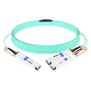
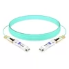
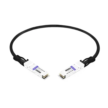
A QSFP112 DAC, or Direct Attach Copper cable, is a pre-terminated copper twinax cable assembly with QSFP112 connectors. It connects two QSFP112-capable ports and transmits high-speed electrical signals directly through copper conductors without optical conversion.
Unlike optical transceivers, DAC cables do not require lasers, photodetectors, optical engines, or fiber coupling components. This makes DAC the simplest and lowest-cost interconnect option for short-reach 400G links.
Passive QSFP112 DAC cables do not contain retimers, DSPs, or active signal-conditioning circuitry in the high-speed signal path. They usually include EEPROM for cable identification and management, but the actual data signal travels through passive copper conductors. This is why passive DAC cables consume extremely low power compared with AOC or optical transceiver solutions.
For short-reach connections within a data center rack, this direct copper path delivers 400G bandwidth with very low latency, low power consumption, and excellent cost efficiency.
QSFP112 DAC vs QSFP112 Optical Transceiver
Choose QSFP112 DAC when the connection distance is within the cable’s supported reach. For passive QSFP112 DAC, this is typically 0.5 m to 2 m for 400G Ethernet applications, depending on cable gauge, host SerDes capability, and vendor qualification. Some InfiniBand-qualified passive copper cables may support slightly longer reaches, but this must always be verified against the switch, NIC, and cable vendor compatibility list.
Choose a QSFP112 optical transceiver when the link distance goes beyond copper reach. Optical modules are required for longer runs such as inter-rack, row-to-row, building-to-building, or campus connections. For example, QSFP112 SR4 can support short multimode fiber links, while QSFP112 DR4, FR4, and LR4 are used for longer single-mode fiber applications.
In simple terms, DAC is the right choice for intra-rack and very short inter-rack connections. Optical modules are necessary when distance, cable weight, fiber infrastructure, or EMI immunity becomes more important than the lowest possible cost.
QSFP112 DAC Types: Passive vs Active
Passive QSFP112 DAC
Passive QSFP112 DAC cables use copper twinax conductors with no retimer, CDR, or active equalization in the high-speed signal path. The host switch or NIC SerDes drives the signal directly through the copper cable to the receiving port.
Key specifications:
Reach: typically 0.5 m to 2 m for 400G Ethernet applications
Power consumption: usually less than 0.1 W per end for the cable assembly
Latency: extremely low, with only signal propagation delay through copper
Cost: the lowest per-link 400G interconnect option for short distances
Passive DAC is the default choice when the required distance fits within its reach limit. At 100G/lane or 112G-class PAM4, copper signal attenuation becomes much more severe than at lower lane rates. A QSFP56 passive DAC operating at 50G/lane may reach 3 m to 5 m in some deployments, but a QSFP112 passive DAC usually has a shorter practical reach, often around 0.5 m to 2 m for 400G Ethernet.
This shorter reach is not a product weakness. It is a result of high-frequency signal loss, crosstalk, connector performance, and the tighter signal integrity requirements of PAM4 modulation at 100G/lane.
Active QSFP112 DAC: ACC and AEC
Active QSFP112 copper cables use signal-conditioning circuitry inside the connector housing to extend reach beyond what passive copper can reliably support. In the market, these products may be described as ACC or AEC, but the two are not exactly the same.
ACC, or Active Copper Cable, typically uses analog equalization or signal conditioning to compensate for copper channel loss. It is usually lower power than a fully retimed solution.
AEC, or Active Electrical Cable, usually includes retimers or DSP-based signal regeneration. This provides stronger signal recovery and can support longer reach, but it also consumes more power and adds slightly more latency.
Key specifications:
Reach: typically 2 m to 5 m, with some vendor-qualified solutions extending farther
Power consumption: ACC is usually lower power, while retimed AEC can consume several watts per end
Latency: slightly higher than passive DAC, especially when retimers are used
Cost: higher than passive DAC, but often still more economical than optical solutions for short-to-medium links
Choose active copper when the connection distance exceeds passive DAC limits but still does not justify AOC or optical transceivers. Active copper can bridge the gap between passive DAC and optical cabling, especially in dense AI and HPC clusters where cost and power are still important.
Cable Gauge: AWG Considerations
Cable gauge affects reach, flexibility, cable bulk, and bend radius. For QSFP112 DAC, common cable gauges include 26 AWG, 28 AWG, and 30 AWG.
26 AWG cables are thicker and provide better signal integrity over longer passive copper distances. They are better suited for structured cabling, cable trays, and longer in-rack runs. However, they are less flexible and can be harder to manage in dense switch deployments.
28 AWG cables provide a balanced option. They offer moderate reach, moderate flexibility, and are commonly used in general-purpose deployments where cable density and signal margin both matter.
30 AWG cables are thinner and more flexible. They are easier to route in high-density patching environments, but they usually support shorter distances, often around 1 m or less for passive QSFP112 applications.
In general, lower AWG numbers mean thicker copper conductors, better signal integrity, and longer reach. Higher AWG numbers mean thinner cables, better flexibility, and easier cable management, but shorter reach.
For high-density QSFP112 switches, cable bulk and airflow should not be ignored. A technically valid 26 AWG cable may be harder to deploy cleanly than a shorter 30 AWG cable, especially in racks with many 400G ports.
QSFP112 DAC vs QSFP-DD DAC: Key Differences
Form Factor Architecture
QSFP112 and QSFP-DD can both support 400G interconnects, but they use different electrical and mechanical architectures.
QSFP112 uses a four-lane architecture. Each lane operates at 100G/112G-class PAM4 signaling, allowing the module to deliver 400G aggregate bandwidth through four high-speed electrical lanes.
QSFP-DD was originally designed as a double-density QSFP form factor with up to eight electrical lanes. Many 400G QSFP-DD DACs use 8 x 50G PAM4 lanes to deliver 400G aggregate bandwidth. The QSFP-DD connector adds a second row of electrical contacts to increase lane count while maintaining a form factor broadly related to the QSFP family.
In practical terms, QSFP112 achieves 400G by increasing the per-lane speed, while traditional 400G QSFP-DD achieves 400G by increasing the number of lanes.
QSFP112 generally uses:
4 x 100G/112G-class PAM4 electrical lanes
A standard QSFP-style mechanical envelope
A single-row QSFP-style host interface
A QSFP112-capable host port with 100G/lane SerDes
Traditional 400G QSFP-DD generally uses:
8 x 50G PAM4 electrical lanes
A double-density QSFP-style connector
A second row of electrical contacts
A QSFP-DD host port designed for higher lane density
Because the two form factors are mechanically and electrically different, QSFP112 DAC and QSFP-DD DAC are not interchangeable. The correct cable must match the host port type and the switch/NIC platform.
Performance Comparison
The higher per-lane rate of QSFP112 creates more challenging signal integrity conditions in copper. At 100G/lane PAM4, copper cable attenuation is significantly higher than at 50G/lane PAM4. This is why QSFP112 passive DAC reach is typically shorter than traditional 400G QSFP-DD DAC reach.
However, QSFP112 also has important advantages. Its four-lane architecture reduces the number of host SerDes lanes required for each 400G port. This can simplify PCB routing, reduce lane count, and help lower power consumption at the switch ASIC and host interface level.
QSFP-DD, by contrast, uses more electrical lanes for traditional 400G implementations. This can provide a longer passive copper reach in some cases, but it also increases connector density, routing complexity, and host-side lane count.
Neither architecture is universally better. The right choice depends on the switch platform, port type, network architecture, cable reach, and upgrade strategy.
When to Choose QSFP112 DAC vs QSFP-DD DAC
Choose QSFP112 DAC when:
Your switch, NIC, or adapter uses QSFP112-native ports
You are deploying 100G/lane architecture for 400G networking
You need low power consumption per 400G port
Connection distances are within the supported DAC reach
You are building AI, HPC, or InfiniBand NDR environments that use QSFP112 adapters
Your platform vendor has qualified QSFP112 DAC or active copper cables for the link
Choose QSFP-DD DAC when:
Your switch platform uses QSFP-DD ports
Your existing infrastructure is based on QSFP-DD cages
You are using traditional 400G QSFP-DD systems based on 8 x 50G PAM4 lanes
You need a longer passive copper reach than QSFP112 can typically provide
You want compatibility with QSFP-DD-based upgrade paths, including QSFP-DD800 platforms where supported
One important point: NVIDIA ConnectX-7 adapters are available in different port form factors, including QSFP112 and OSFP versions. NVIDIA Quantum-2 switches commonly use OSFP switch-side cages. Therefore, in NVIDIA InfiniBand NDR deployments, the correct cable may be QSFP112-to-QSFP112, OSFP-to-QSFP112, or another platform-specific assembly. Always confirm the exact NIC, switch port, and vendor cable qualification before selecting the cable.
QSFP112 DAC vs AOC: When to Choose Copper
Side-by-Side Comparison
QSFP112 passive DAC is the lowest-cost and lowest-power choice for very short links. Its maximum reach is usually around 0.5 m to 2 m for 400G Ethernet, with extremely low power consumption and near-zero added latency. The trade-off is that the cable is heavier, less flexible, and more limited in reach.
QSFP112 active copper extends the reach beyond passive DAC. It is useful for links around 2 m to 5 m, depending on the cable type and vendor qualification. ACC solutions generally consume less power, while retimed AEC solutions consume more power but provide stronger signal recovery. Active copper costs more than passive DAC but may still be more economical than optical cabling for short-to-medium distances.
QSFP112 AOC, or Active Optical Cable, supports much longer reach, often up to 100 m depending on the product. It is lighter, thinner, more flexible, and immune to electromagnetic interference. However, it consumes more power than passive DAC and usually costs significantly more.
In simple terms:
Passive DAC is best for the shortest and lowest-cost links.
Active copper is best when passive DAC is too short but optics are unnecessary.
AOC is best when reach, flexibility, weight, or EMI immunity matters more than the lowest possible cost.
Decision Framework
Use QSFP112 passive DAC for:
Intra-rack connections under 2 m
Cost-sensitive deployments with hundreds or thousands of short links
Environments where power consumption must be minimized
Low-latency applications such as HPC and AI training
Short links between adjacent switches, servers, NICs, or DPUs
Use QSFP112 active copper for:
Short inter-rack links beyond passive DAC reach
Links around 2 m to 5 m where optics are not required
AI cluster cabling where cost and power remain critical
Deployments where AOC is technically possible but economically unnecessary
Use QSFP112 AOC for:
Inter-rack connections between several meters and 100 m
Environments with high electromagnetic interference
Deployments requiring thin, flexible, and lightweight cables
Connections where cable routing is complex
Situations where copper cable weight or bend radius becomes a problem
Cost Analysis at Rack Scale
The cost difference between DAC and AOC compounds quickly at rack scale. Consider a 64-port QSFP112 leaf switch.
If all 64 links use passive DAC cables priced around $30 to $50 per cable, the total cable cost is approximately $1,920 to $3,200.
If all 64 links use AOC cables priced around $100 to $200 per cable, the total cable cost is approximately $6,400 to $12,800.
This means the cabling cost difference alone can reach several thousand dollars per switch. In large AI clusters with hundreds of switches and thousands of 400G links, the savings from using DAC for short-reach connections can become substantial.
Power savings also matter. Passive DAC consumes almost no power compared with AOC or optical modules. Depending on the AOC power specification, using DAC for short links can reduce switch-side power consumption by tens or even hundreds of watts per fully populated switch. This also lowers cooling demand and improves rack-level power efficiency.
QSFP112 DAC Specifications and Signal Integrity
Electrical Specifications
QSFP112 DAC cables must meet strict electrical requirements for 100G/lane PAM4 signaling.
Key electrical characteristics include:
Lane architecture: 4 x 100G/112G-class PAM4 electrical lanes
Aggregate bandwidth: 400G
Signaling: PAM4, or Pulse Amplitude Modulation with four levels
Typical Ethernet electrical lane signaling: 53.125 GBd PAM4, corresponding to 106.25 Gb/s per lane
Signal integrity requirements: defined by the relevant IEEE, OIF, and platform-specific channel specifications
FEC dependency: high-speed PAM4 links rely on forward error correction to achieve reliable post-FEC performance
The exact BER target depends on the host channel, protocol, FEC implementation, and test methodology. For Ethernet applications, compliance is normally evaluated against IEEE electrical interface requirements and FEC performance expectations rather than one universal pre-FEC BER number.
Why Reach Is Limited at 100G/lane
Signal attenuation in copper increases with frequency. At 100G/lane PAM4, the copper channel is much more difficult than at 50G/lane PAM4. Higher symbol rates mean the signal is more sensitive to cable loss, crosstalk, reflections, connector quality, and manufacturing tolerance.
The main limiting factors include:
Greater insertion loss per meter of copper cable
Higher crosstalk between adjacent conductors
More sensitivity to connector and PCB channel quality
Tighter tolerance on cable construction and shielding
Reduced signal margin at the receiver
These physical constraints explain why QSFP112 passive DAC reach is usually shorter than QSFP56 or traditional 400G QSFP-DD passive DAC reach.
Active copper cables compensate for some of these losses by adding equalization, retiming, or signal regeneration inside the connector housing. This extends reach but also increases power consumption, cost, and latency.
Standards Compliance
QSFP112 DAC cables are typically designed around multiple standards and specifications.
Relevant specifications include:
QSFP112 MSA for mechanical form factor, host interface, and cage/connector requirements
IEEE 802.3ck for 100G/lane electrical interfaces used in 100G, 200G, and 400G Ethernet systems
OIF CEI-112G for 112G-class electrical channel specifications
CMIS 5.x for module and cable management, depending on vendor implementation
Older QSFP management specifications such as SFF-8636 are more closely associated with previous QSFP generations. For QSFP112 products, CMIS-based management is more commonly referenced, especially for modern 400G and 800G interconnect ecosystems.
Installation and Troubleshooting
Pre-Deployment Checklist
Before installing QSFP112 DAC cables, check the following items:
Verify switch port support. Confirm that the port is QSFP112-capable and supports the required 400G mode.
Check adapter and NIC compatibility. Make sure the server-side adapter supports QSFP112 DAC at the intended speed and protocol.
Confirm firmware version. Update switch, NIC, and adapter firmware when required for cable recognition, CMIS support, and stable link training.
Confirm cable length. Measure the actual routing path and add reasonable slack. Do not assume a straight-line distance is enough.
Check vendor qualification. Use cables listed on the switch or NIC vendor compatibility list whenever possible.
Inspect connectors. Check for bent contacts, contamination, latch damage, or physical deformation.
Verify polarity and link type. Most straight-through DAC cables are used for standard port-to-port connections, while breakout or special assemblies require additional verification.
Plan cable routing. Respect bend radius, avoid sharp kinks, and ensure that cable bundles do not block switch airflow.
Common Issues and Solutions
No link or intermittent link:
Re-seat the cable firmly in both ports.
Verify that the cable is fully inserted and the latch is locked.
Confirm that the switch port is enabled.
Check that both ports are configured for the same speed and protocol.
Verify that the cable type matches the port type.
Check switch and NIC firmware compatibility.
Test with a known-good cable to isolate the issue.
High BER or FEC errors:
Check cable length against the vendor specification.
Inspect the cable for kinks, crushing, or tight bends.
Verify that the AWG is appropriate for the required distance.
Avoid routing high-speed copper cables through areas with excessive stress or compression.
Confirm that the cable is qualified for the specific switch and NIC combination.
Check host-side FEC counters and lane error statistics.
Replace the cable if errors persist after re-seating and reconfiguration.
Connector seating issues:
Ensure the cable is fully inserted until the latch clicks.
Check for obstructions inside the port cage.
Verify that the connector form factor matches the port.
Do not force QSFP112, QSFP-DD, or OSFP cables into incompatible ports.
Inspect the pull-tab and latch mechanism for damage.
Monitoring and Diagnostics
QSFP112 DAC cables can expose cable identification and management information through the host management interface. For passive DAC, this usually includes information such as vendor name, part number, serial number, cable length, cable type, and supported speed.
However, passive DAC cables do not include optical components, so optical TX/RX power, laser bias current, and optical wavelength diagnostics do not apply. Full DOM or DDM functions may not be implemented on passive DAC products.
For active copper cables, additional diagnostic information may be available depending on the vendor and cable design. Retimed AEC products may expose more management data than passive DAC cables.
During operation, engineers should monitor:
Port link status
Lane status
Pre-FEC and post-FEC error counters
FEC correction statistics
Link flaps
Module or cable temperature where supported
Host-side voltage and port health information
Most meaningful BER and FEC diagnostics come from the switch or NIC rather than the passive cable itself.
Frequently Asked Questions
What is a QSFP112 DAC cable?
A QSFP112 DAC, or Direct Attach Copper cable, is a high-speed copper cable assembly used to connect QSFP112-capable 400G network ports without optical conversion. It uses twinax copper conductors and QSFP112 connectors to transmit 400G signals over short distances.
What is the maximum length of QSFP112 DAC?
Passive QSFP112 DAC cables typically support 0.5 m to 2 m for 400G Ethernet applications. Some platform-qualified InfiniBand passive copper cables may support longer lengths, but this depends on the switch, NIC, cable gauge, and vendor qualification.
Active QSFP112 copper cables can typically support around 2 m to 5 m, and some vendor-qualified products may extend farther. Always check the cable datasheet and the platform compatibility list before deployment.
Is QSFP112 DAC passive or active?
Both options exist. Passive QSFP112 DAC cables use passive copper conductors in the high-speed signal path and consume extremely low power. Active QSFP112 copper cables include signal-conditioning circuitry such as equalizers, retimers, or DSPs to extend reach.
Passive DAC is best for the shortest and lowest-power links. Active copper is better when passive DAC cannot meet the required distance but optical cabling is not necessary.
What is the difference between QSFP112 DAC and QSFP-DD DAC?
QSFP112 DAC uses a four-lane 100G/112G-class PAM4 architecture in a QSFP-style form factor. Traditional 400G QSFP-DD DAC uses a double-density QSFP connector with up to eight electrical lanes, commonly 8 x 50G PAM4 for 400G applications.
QSFP112 reduces the number of lanes required for 400G, which can simplify host-side SerDes architecture and reduce lane count. QSFP-DD provides a higher-density connector architecture and is widely used in 400G and 800G migration paths. The two cable types are not interchangeable and must match the host port.
Can QSFP112 DAC work with NVIDIA ConnectX-7?
Yes, QSFP112 DAC can work with NVIDIA ConnectX-7 adapters that use QSFP112 ports, provided the cable is qualified for the adapter, switch, speed, and protocol.
However, not all ConnectX-7 adapters use QSFP112 ports. Some versions use OSFP. NVIDIA Quantum-2 switches commonly use OSFP switch-side cages, so many NDR deployments may require OSFP-to-QSFP112 copper cables, OSFP-to-OSFP cables, or other platform-specific assemblies.
Before selecting a cable, confirm the exact port form factor on both ends and check NVIDIA or the system vendor’s qualified cable list.
Conclusion
QSFP112 DAC cables provide one of the most cost-effective and power-efficient ways to build short-reach 400G links. For intra-rack and very short inter-rack connections, passive QSFP112 DAC offers the lowest cost, lowest latency, and lowest power consumption.
When passive DAC reach is not enough, active copper cables can extend the link distance while still avoiding the cost and power of optical transceivers. For longer runs, complex routing, or environments where cable weight and flexibility matter, QSFP112 AOC or optical transceivers become the better choice.
The most important rule is simple: match the cable to the port, distance, protocol, and platform qualification. QSFP112, QSFP-DD, and OSFP are not interchangeable just because they all support 400G. In high-density AI and data center networks, correct cable selection directly affects link stability, power consumption, cooling design, and total deployment cost.