


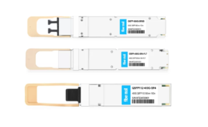
800G SR8 and 400G SR4 Optical Transceiver Modules Compatibility and Interconnection Test Report
Version Change Log Writer V0 Sample Test Cassie Test Purpose Test Objects:800G OSFP SR8/400G OSFP SR4/400G Q112 SR4. By conducting corresponding tests, the test parameters meet the relevant industry standards,
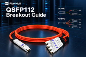
QSFP112 Breakout Guide: 400G to 2x200G and 4x100G
A 400G QSFP112 port looks straightforward: four high-speed electrical lanes combine to deliver one 400G interface. Breakout seems equally simple—divide those lanes into two 200G links or four 100G links.
QSFP112 Price Guide 2026: 400G Module Costs, Cost Per Port and Volume Tiering
The same 400G DR4 optic can sell for around $500 from a factory-direct supplier and more than $1,400 from some vendor list price channels. Four price points, one standard, and
QSFP112 Compatibility Guide: Switches, NICs and CMIS
Priya spent most of a Tuesday morning troubleshooting a link that should have taken four minutes to bring up. She inserted a 400G QSFP112 module into an older leaf switch

QSFP112 Module Types: VR4, SR4, DR4, FR4 and LR4 Compared
Send a request for “a 400G QSFP112 module” to three different vendors and you may receive three different recommendations. One vendor may quote a DR4. Another may suggest a DR4+. A
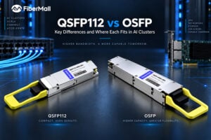
QSFP112 vs OSFP: Choosing the Right 400G Form Factor
At first glance, QSFP112 and OSFP look like two competing form factors for high-speed networking. Both appear in 400G systems, both support PAM4 signaling, and both are widely used in
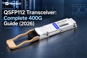
QSFP112 Transceiver: Complete 400G Guide (2026)
Ask five network engineers whether they should deploy QSFP112 or QSFP-DD for a 400G network, and you may get five different answers. Both form factors can support 400G, both are