


Selecting the right 400G transceiver for multimode fiber involves many factors. Here are some of the key considerations:
Distance: The range of operations for each type of transceiver varies. Before choosing a transceiver, you should know the exact distance between the systems you plan to connect. Short-range transceivers are typically used for distances up to 70m, while long-range variants can cover distances above 2km.
Power Consumption: Power usage can vary substantially from one transceiver type to another. Higher capacity transceivers often use more power. Ideally, you should aim for a transceiver that offers the required data rate at the lowest possible power consumption.
Cost: Pricing can vary significantly between different transceivers. The overall cost should be evaluated in the context of your specific networking needs and budgetary constraints.
Compatibility: Not all transceivers will be compatible with your switches, routers, or other network devices. Be sure to confirm that the transceiver you choose works with your existing hardware.
Interconnection: Consider how different transceivers suit your interconnection environments. Transceivers come in different form factors such as QSFP-DD, OSFP, CFP2, CFP8, or COBO, and each has its own specifications for things like power consumption, size, and interface.
Reliability and Durability: The lifespan and durability of the transceivers also come into play. High-quality transceivers are built to last, reducing the need for replacements and maintenance.
The key features and common applications of each of these transceivers are described below.
1.The OSFP-400G-SR8 / SR8-C and QDD-400G-SR8 / SR8-C
The 400G-SR8 was the first 400G MMF transceiver available and has been deployed for point-to-point 400GE applications, such as leaf-to-spine connectivity, illustrated below.
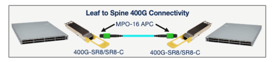
While the 400G-SR8 provides cost-effective 400GE connectivity over MMF, it requires 16 fibers per transceiver and uses an MPO-16 APC fiber connector. Most 40G and 100G parallel MMF optics (such as the 40G-SR4 and 100G-SR4) use MPO-12 UPC fiber connectors. MPO-16 to 2x MPO-12 patch cables are required to use a 400G-SR8/SR8-C transceiver over an MPO-12 UPC-based fiber plant.
Another key application for 400G-SR8 transceivers is optical breakout into 2x 200G-SR4 links, enabling TOR-to-host connectivity where 200G to the host is required, as illustrated below.
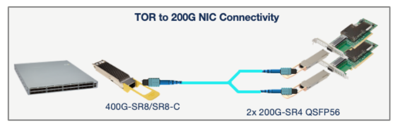
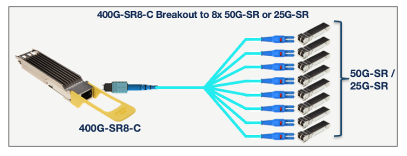
The 400G-SR8-C transceiver has the same features as the 400G-SR8, with the added ability to breakout into 8x 50G-SR or 8x 25G-SR optical links. It can therefore be used in applications that require high-density 50G or 25G breakouts – as illustrated below.
- The OSFP-400G-SRBD and QDD-400G-SRBD, or “400G-BIDI”transceivers.
400G-BIDI transceivers use the widely deployed MPO-12 UPC connector for parallel multimode fiber. This allows existing 40G or 100G links that use 40G-SR4 or 100G-SR4 QSFP optics to be upgraded to 400GE with no change to the fiber plant, as illustrated below:
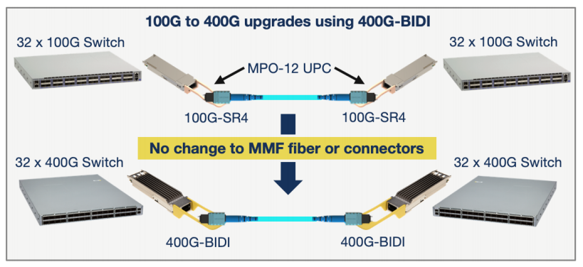
When configured for 400GE operation, the 400G-BIDI transceiver is compliant with the IEEE 400GBASESR4.2 specification for 400GE over 4 pairs of MMF.
Arista’s 400G-BIDI transceivers are also capable of breaking out into 4x 100GE links and can be configured (via EOS) to interoperate either with the widely deployed base of 100G-BIDI (100G-SRBD) transceivers, or newer 100G-SR1.2 transceivers, as indicated below.
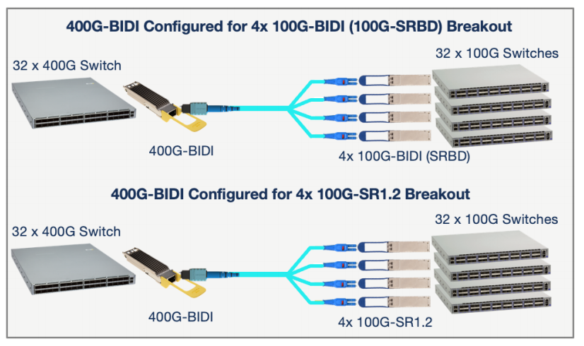
In summary, Arista’s 400G-BIDI transceiver is software configurable to operate in any one of three operating modes:
i) 400G-SR4.2 for point-to-point 400GE links
ii) 4x 100G-BIDI for breakout and interop with 4x 100G-BIDI (100G-SRBD) transceivers
iii) 4x 100G-SR1.2 for breakout and interop with 4x 100G-SR1.2 transceivers
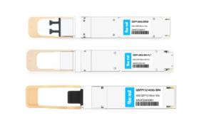
800G SR8 and 400G SR4 Optical Transceiver Modules Compatibility and Interconnection Test Report
Version Change Log Writer V0 Sample Test Cassie Test Purpose Test Objects:800G OSFP SR8/400G OSFP SR4/400G Q112 SR4. By conducting corresponding tests, the test parameters meet the relevant industry standards, and the test modules can be normally used for Nvidia (Mellanox) MQM9790 switch, Nvidia (Mellanox) ConnectX-7 network card and Nvidia (Mellanox) BlueField-3, laying a foundation for
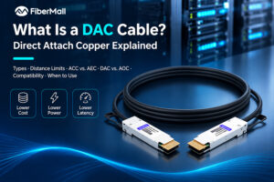
What Is a DAC Cable? Direct Attach Copper Explained
A DAC cable, or direct attach copper cable, is a fixed-length twinax copper cable assembly with transceiver-style connectors permanently attached to both ends. It connects servers, switches, and storage devices over short distances without requiring separate optical transceivers. Because it carries electrical signals over copper rather than converting them to

Optical Interconnect Quality Management for AI Clusters
As AI infrastructure evolves toward increasingly large GPU clusters, optical interconnect reliability is becoming a critical factor in overall computing performance. Modern AI data centers rely on thousands or even hundreds of thousands of optical links connecting GPUs, switches, NICs, and storage systems. A single unstable link can introduce retransmissions,
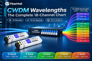
CWDM Wavelengths: The Complete 18-Channel Chart
The CWDM wavelength grid covers 18 nominal center wavelengths from 1271 to 1611 nm, spaced 20 nm apart under ITU-T G.694.2. Many conventional CWDM links use the eight higher-wavelength channels, from 1471 through 1611 nm, because they avoid the water-peak region that can cause high attenuation on older single-mode fiber.

102.4T NPO Switch Design: Near-Package Optics for AI Scale-Up Networks
As AI clusters grow from hundreds to thousands of accelerators, traditional electrical and pluggable optical interconnects face increasing challenges in bandwidth density, power consumption, and signal integrity. A 102.4T NPO switch (Near-Packaged Optics switch) addresses these limitations by placing optical engines close to the switching ASIC, shortening high-speed electrical paths and
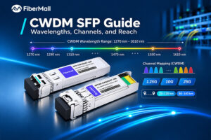
CWDM SFP Guide: Wavelengths, Channels, and Reach
The number on the CWDM SFP label is not the number on the mux port. A module arrives marked 1470 nm. The port it needs to reach is labeled CH11. Neither label mentions the other, and nothing in the box explains that they describe the same channel. That single gap
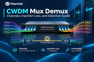
CWDM Mux Demux: Channels, Insertion Loss, and Selection Guide
The 18-channel CWDM mux demux can look like the safest purchase: room to grow, one part number, and no second trip to procurement. Then the link budget arrives. An 18-channel unit may add around 5.0 to 5.4 dB of insertion loss, while an 8-channel unit may add around 2.4 dB.