

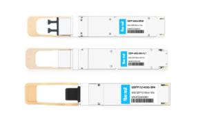
The 400G-BIDI Module from Arista is Capable of being Broken out into 4x 100G-BIDI or 4x 100G-SR1.2 Links. What is the Difference Between 100G-BIDI and 100G-SR1.2?

Picture of FiberMall

FiberMall

Answered on 9:02 am

The difference between 100G-BIDI and 100G-SR1.2 is mainly in the number of optical lanes and the modulation solution. 100G-BIDI uses two optical lanes, one for each direction, over a duplex LC multi-mode fiber. 100G-SR1.2 uses four optical lanes, two for each direction, over the same fiber. 100G-BIDI uses NRZ (Non-Return-to-Zero) modulation, which means each bit is encoded as a single symbol. 100G-SR1.2 uses PAM4 (Pulse Amplitude Modulation) modulation, which means each symbol encodes two bits. PAM4 enables higher data rates with lower baud rates, but also introduces more noise and complexity. Both 100G-BIDI and 100G-SR1.2 are compliant to IEEE802.3bm 100GBASE-SR4 standard. The main advantage of 100G-BIDI is that it can reuse the existing 40G-BIDI infrastructure and reduce the fiber cabling cost. The main advantage of 100G-SR1.2 is that it can interoperate with 400G-SR4.2 and provide a future-proof solution for higher bandwidth demand.

Another difference between 100G-BIDI (100G-SRBD) and 100G-SR1.2 is the FEC (Forward Error Correction) used. 100G-BIDI (100G-SRBD) modules have been widely deployed for 100G operation over duplex MMF and use a FEC implementation that was developed prior to the IEEE standardization of KP-FEC for 50G PAM-4 based modules. Because of the differences in FEC implementation, 100G-SRBD and 100G-SR1.2 modules are not interoperable with each other.

People Also Ask

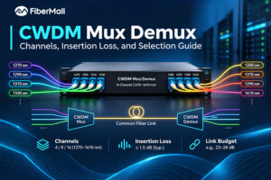
CWDM Mux Demux: Channels, Insertion Loss, and Selection Guide

The 18-channel CWDM mux demux can look like the safest purchase: room to grow, one part number, and no second trip to procurement. Then the link budget arrives. An 18-channel unit may add around 5.0 to 5.4 dB of insertion loss, while an 8-channel unit may add around 2.4 dB.

USFP Capacity Explained: From 6.4T to 12.8T AI Fabric Bandwidth

USFP is designed to scale from 6.4T to 12.8T by increasing its electrical lane count while supporting 400 Gb/s per lane. Its first planned transceivers use 16 full-duplex lanes, delivering 6.4 Tb/s of aggregate capacity. The connector architecture is designed to support future expansion to 32 lanes, potentially enabling 12.8

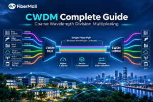
CWDM Complete Guide: Coarse Wavelength Division Multiplexing

Consider an illustrative scenario: a nine-building hospital campus has one spare fiber pair, and a new imaging center is opening in six weeks. Installing additional duct would take eight months. Daniel, the network engineer on the project, needs nine 10G services running over the fiber pair the hospital already owns.

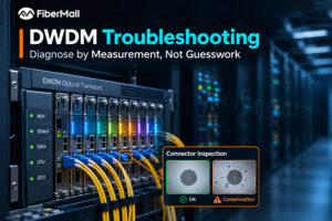
DWDM Troubleshooting: Diagnose by Measurement, Not Guesswork

A link runs clean for two years. Then one Tuesday, two edge channels start throwing errors while the other thirty-eight remain healthy. The amplifier raises an alarm, so someone replaces it. The errors return a week later because the amplifier was never the problem. That sequence is common enough to

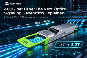
400G per Lane: The Next Optical Signaling Generation, Explained

400G per lane refers to a nominal data rate of 400 gigabits per second (Gb/s) carried by a single electrical lane or optical data channel, depending on the interface being discussed. It represents the next step beyond the 200G-per-lane signaling used in 1.6T-class modules. For electrical interfaces, the industry often

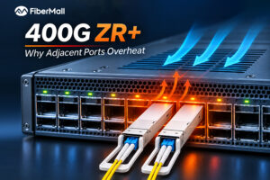
400G ZR+ Coherent Transceivers: Why They Overheat Adjacent Ports — and How to Fix It

400G ZR+ coherent transceivers are changing how operators build high-capacity optical networks. By integrating coherent signal processing into compact QSFP-DD and OSFP modules, they enable long-distance 400G connectivity directly from compatible switches and routers, reducing dependence on separate optical transport equipment. But this integration creates a thermal challenge. A conventional

Related Articles

800g sr8 and 400g sr4

800G SR8 and 400G SR4 Optical Transceiver Modules Compatibility and Interconnection Test Report

Version Change Log Writer V0 Sample Test Cassie Test Purpose Test Objects:800G OSFP SR8/400G OSFP SR4/400G Q112 SR4. By conducting corresponding tests, the test parameters meet the relevant industry standards, and the test modules can be normally used for Nvidia (Mellanox) MQM9790 switch, Nvidia (Mellanox) ConnectX-7 network card and Nvidia (Mellanox) BlueField-3, laying a foundation for
Read More »
usfp capacity

USFP Capacity Explained: From 6.4T to 12.8T AI Fabric Bandwidth

USFP is designed to scale from 6.4T to 12.8T by increasing its electrical lane count while supporting 400 Gb/s per lane. Its first planned transceivers use 16 full-duplex lanes, delivering 6.4 Tb/s of aggregate capacity. The connector architecture is designed to support future expansion to 32 lanes, potentially enabling 12.8
Read More »
cwdm

CWDM Complete Guide: Coarse Wavelength Division Multiplexing

Consider an illustrative scenario: a nine-building hospital campus has one spare fiber pair, and a new imaging center is opening in six weeks. Installing additional duct would take eight months. Daniel, the network engineer on the project, needs nine 10G services running over the fiber pair the hospital already owns.
Read More »
DWDM troubleshooting

DWDM Troubleshooting: Diagnose by Measurement, Not Guesswork

A link runs clean for two years. Then one Tuesday, two edge channels start throwing errors while the other thirty-eight remain healthy. The amplifier raises an alarm, so someone replaces it. The errors return a week later because the amplifier was never the problem. That sequence is common enough to
Read More »
400G per lane

400G per Lane: The Next Optical Signaling Generation, Explained

400G per lane refers to a nominal data rate of 400 gigabits per second (Gb/s) carried by a single electrical lane or optical data channel, depending on the interface being discussed. It represents the next step beyond the 200G-per-lane signaling used in 1.6T-class modules. For electrical interfaces, the industry often
Read More »
400G ZR+

400G ZR+ Coherent Transceivers: Why They Overheat Adjacent Ports — and How to Fix It

400G ZR+ coherent transceivers are changing how operators build high-capacity optical networks. By integrating coherent signal processing into compact QSFP-DD and OSFP modules, they enable long-distance 400G connectivity directly from compatible switches and routers, reducing dependence on separate optical transport equipment. But this integration creates a thermal challenge. A conventional

Read More »
Scroll to Top