After working in optical transceiver industry for a long time, we take it by granted that multi mode corresponds to 850nm, or 850nm, 910nm wavelength. Single mode corresponds to wavelengths of 1260-1650nm, especially wavelengths near the 1310nm band and near the 1550nm band.
The optical communication industry has developed for decades, and people in the industry need to improve efficiency during communication, so we won’t repeat common sense every day. However, we know by chance that there are multimode lasers with a wavelength of 1550nm, and multimode lasers with 1310nm. How does this happen? In fact, 850nm can also be made into a single-mode laser.
Single mode refers to single transverse mode and multimode refers to multi transverse mode in the industry. Wavelength, in fact, expresses the characteristics of the longitudinal mode, and can be divided into single longitudinal mode and multiple longitudinal modes. That is, single-wavelength or multi-wavelength lasers. This wavelength specifically refers to the “amplified” wavelength. Lasers are optical amplifiers based on the principle of interference amplification. So many people say that lasers emit “coherent” light.
What wavelengths correspond to single mode and multi mode? So, the question becomes, what is the relationship between the single transverse mode or multiple transverse modes of the (stimulated emission) optical amplifier and the output range of the longitudinal mode?
Answer: there is no corresponding relationship in theory. The two are orthogonal out of two-dimensional considerations. The 1310nm laser can be either a single transverse mode or a multi-transverse mode. Similarly, 850nm and 1550nm lasers can be designed as a single transverse mode or a multi-transverse mode.
However, we should take into account that a specific industrial chain has been formed in the actual application, which has the best cost performance in some special scenarios. For example, in the scenario based on optical fiber communication, multi-transverse-mode lasers with a wavelength of 850nm have low-cost advantages, and single-transverse-mode lasers based on 1310nm or 1550nm have excellent transmission performance of low dispersion/low loss in optical fibers.
For example, in the lidar industry, for edge-emitting lasers, there is no need to consider the characteristics of a single transverse mode in TOF or AM scenarios. Multi-mode EEL edge-emitting long-wavelength lasers can be manufactured to increase power and reduce eye safety risks. Light has a transmission direction, and the mode along the transmission direction is a longitudinal mode, which is a frequency-dependent characteristic based on “time interference” in the laser.
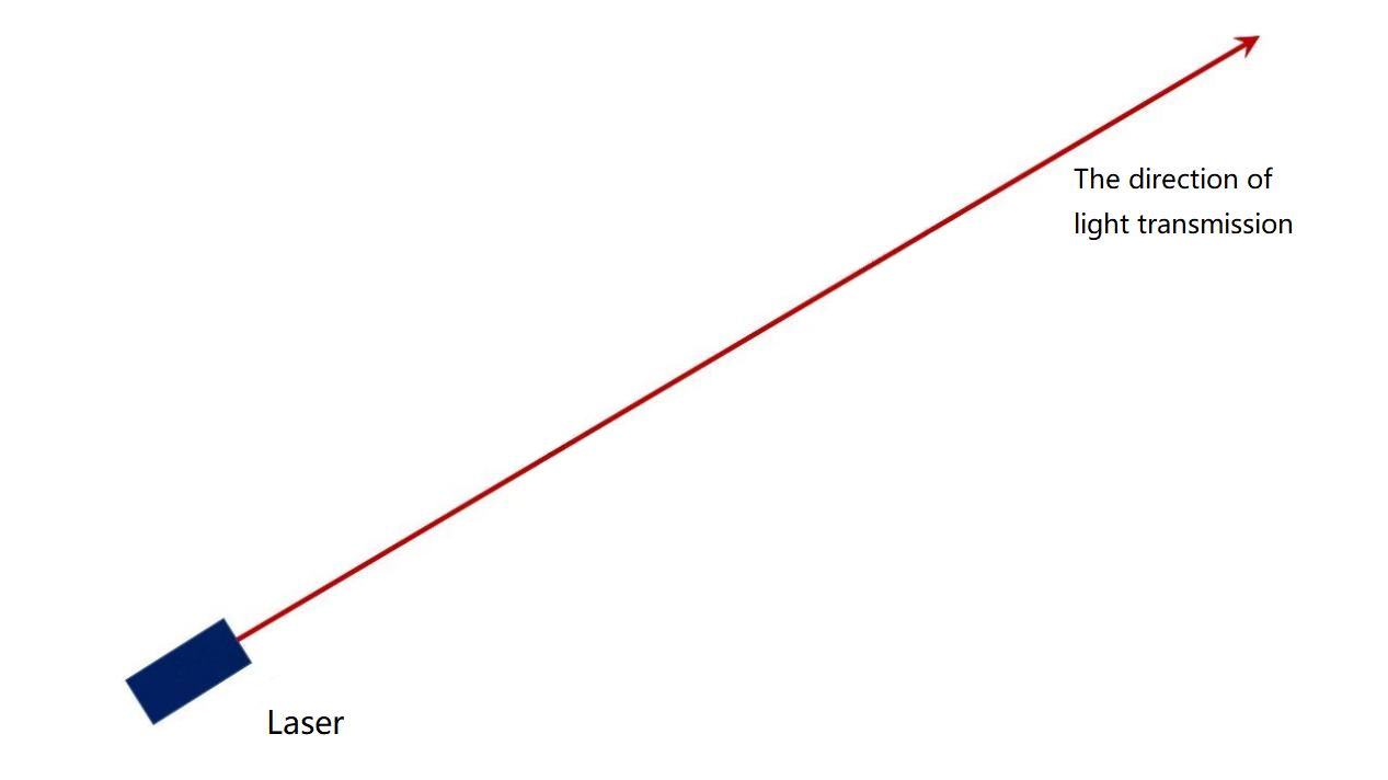
The direction of light transmission of the laser
The light field distribution of the cross-section perpendicular to the transmission direction is a transverse mode, which is based on some distribution characteristics formed by “spatial interference” in the laser.
Anyone who designs lasers knows that there are two solutions in the laser formula-time and space solutions.
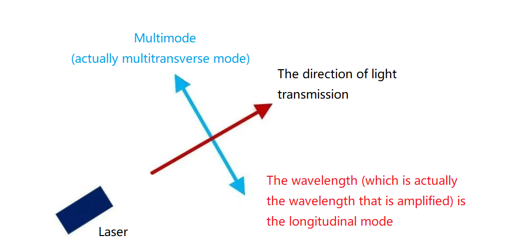
Space-Time Dimensions of Lasers
The transverse mode is based on the energy distribution of the space. This is a distribution that can be seen in real life, and we will talk about it later. The longitudinal mode is the energy distribution based on time and light is transmitted at the speed of light, and there are several parameters of wavelength, (light) speed, fluctuation time and distance. The wavelength cannot be seen with the eyes, so it needs to be tested with a spectrometer, which is actually an optical spectrometer. The frequency of light x the wavelength of light = the speed of light in vacuum C, where C is a constant. Therefore, the frequency can be tested with a spectrum analyzer (for example, ~300THz corresponds to 1.3μm wavelength, and~200THz corresponds to 1.5μm wavelength) and the wavelength can be calculated.
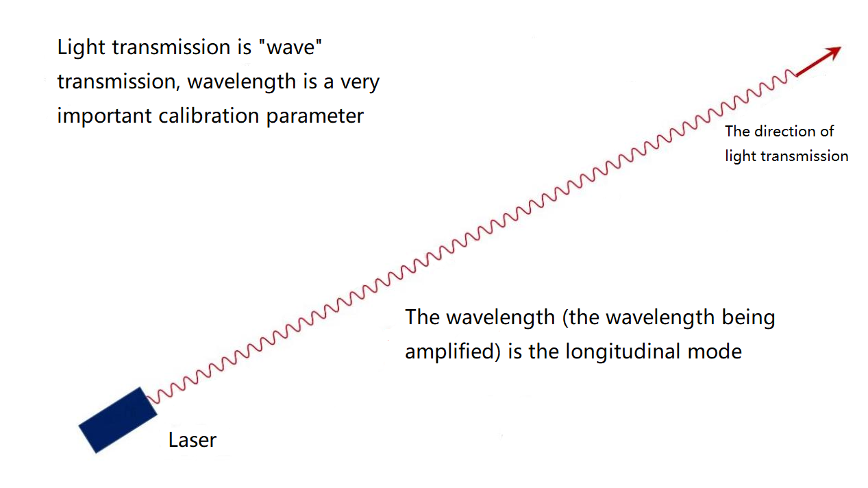
The transmission of light is the transmission of wave
The wavelength we are talking about, in this context, refers specifically to the wavelength range.
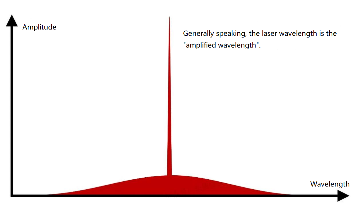
Wavelength is a range
The wavelength range is determined by the gain material. In this range, selecting a specific wavelength for interference is the function of the resonant cavity. Interference can play a role in amplification.
The resonant cavity has a cavity length. The gratings of DFB and VCSEL are all “tiny” cavity lengths. The cavity length and the wave velocity of light can be used to calculate the reflection time of light, and the interference based on time is the longitudinal mode. These longitudinal models have different emphases in our context.
The resonant cavity and the gain are made together, which is the choice of most lasers in optical transceivers, such as VCSEL, DFB, EML and other chips. The resonator (cavity for interference amplification) determines which wavelengths are amplified. The resonant cavity and the gain material choose the same type of material system, such as the GaAs material system for VCSEL, InP material system for DFB and so on.
The resonant cavity and gain material adopt different systems, such as GaAs system for gain and silicon for resonant cavity. This is Huawei’s process of epitaxial GaAs on silicon substrate and making InAs quantum dots in OFC2023, or HP’s silicon-based quantum dot laser. Using InP for gain and silicon for resonator is Intel’s silicon-based integrated laser. Gain material: Determines the range of wavelengths.When the resonator and gain material are produced independently, we have an external cavity laser, that is, a laser composed of resonators “independent of the gain part”.
Going back to the transverse mode again, single mode and multi mode are specifically referred to transverse modes in the industry, which means the energy distribution in space. single mode and multi mode matters in the optical fiber communication, while it is not the case for TOF method of lidar. When there are multiple energy peaks, that is multi-mode, and only one energy peak is single-mode. The spatial fluctuations can be seen with the eyes, when our laser pointer shines on the screen, we can see the distribution of bright spots, which is the embodiment of the transverse mode.
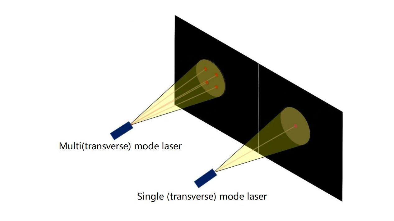
Transverse mode of laser- spot distribution
The VCSEL in optical transceiver is a multi-mode laser, that means there are multiple bright spots. The VCSEL is called vertical cavity surface emission laser. The vertical cavity surface refers to the relative coordinates of the wafer. The resonant cavity is perpendicular to the surface of the wafer, called a vertical cavity. The direction of the resonator is related to the output direction of the laser, which determines the light output direction of the laser without special treatment. It can realize the emission perpendicular to the wafer surface, which can be surface emission or bottom emission.
Single-mode lasers generally emit from the side, either from the left side or the right side, or from both sides at the same time. For edge emission, the output direction of the light is realized by the transverse resonant cavity without other additional processing, the output wavelength range is realized by the gain material, and the transverse spot is determined by the spatial structure of the output waveguide.
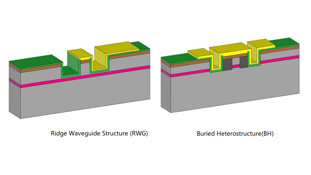
Two common types of waveguide structures used to confine single mode
The space of light is also “fluctuating”. As long as the width is appropriate, there will be no multiple bright spots. As for the design of most optical communication lasers, the waveguide width of the InP material system is about 2 μm, which is common structure for single-mode limitation.
Since it is common, it is not the only one. If the space-limited structure is widened, multiple transverse modes will appear. This was common in lasers in the early years. It became easy to manufacture single mode in optical communication later, and people forgot about it.
In recent years, people are talking about widening the waveguide again, because the output power needs to be increased. For example, FiberMall uses multi-mode to realize DFB+SOA cascade, and then uses the virtual waist to realize single mode. And the 5μm-width lasers that Huawei has made in recent years are essentially multi-transverse modes, with the purpose to increase the output power. Another example is the TOF method in the lidar field, which prefers account high power to single mode and multi-mode. They do not need to be transmitted in optical fibers, so there’s no need to consider this aspect. The following figure is a multi-transverse mode laser with the waveguide width stretched very wide to make the edge emission.
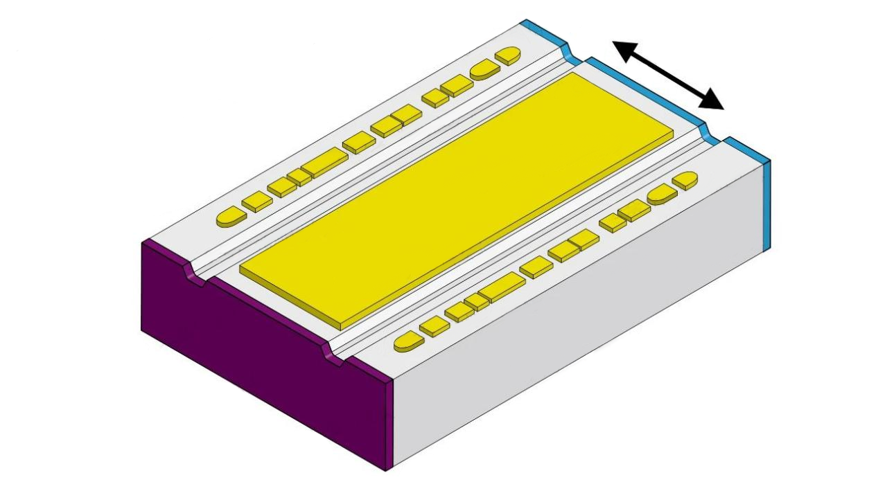
Edge-emitting multimode lasers for lidar
To sum up, in terms of edge-emitting lasers, optical fiber communication has a requirement for single mode, which can be realized. Some application scenarios have local multi-mode designs, and we need additional processing to restore single mode again. This act is intended to meet the needs of optical fiber communication essentially.
The logic behind is that there is an optimal transmission band for the communication technology of the commercial solid glass optical fiber. (Hollow-core fiber is not affected by this band, and OFC2023 tells the progress of hollow-core fiber.) And the materials that meet this wavelength range and can achieve single mode are only InGaAsP/InP, or AlGaInAs/InP. This material system cannot achieve single-mode output in the structure of vertical cavity surface emission and cannot even achieve large-scale industrial manufacturing with high reliability. Therefore, people have to choose edge emission, which is an unfriendly optical path output structure.
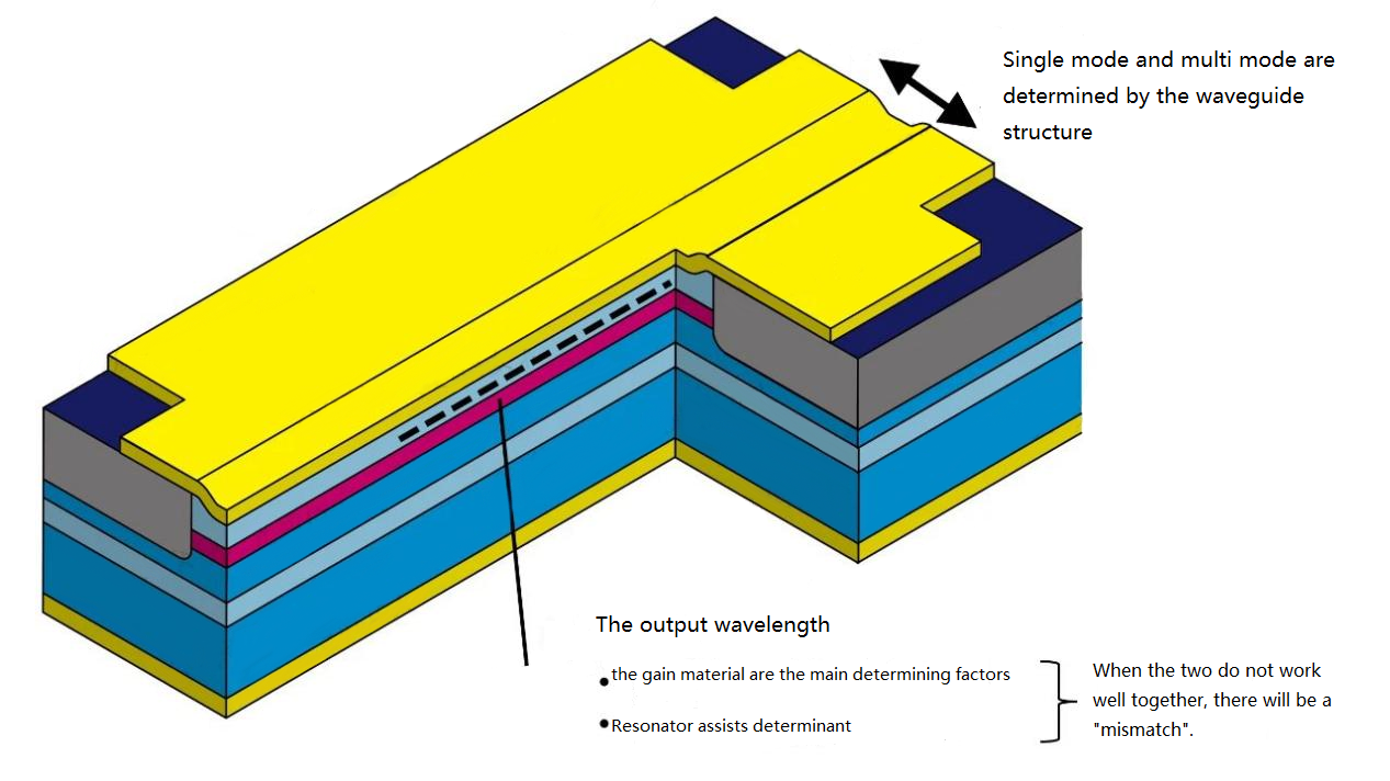
The waveguide structure determines whether it is single mode or multi mode
Surface emission is very cheap, and theoretically can achieve single-mode output, but the industry cannot achieve large-scale, long-term, stable and reliable manufacturing. This is due to the trench etching in this process flow. The groove is etched for side oxidation, which is used to guide the current path.
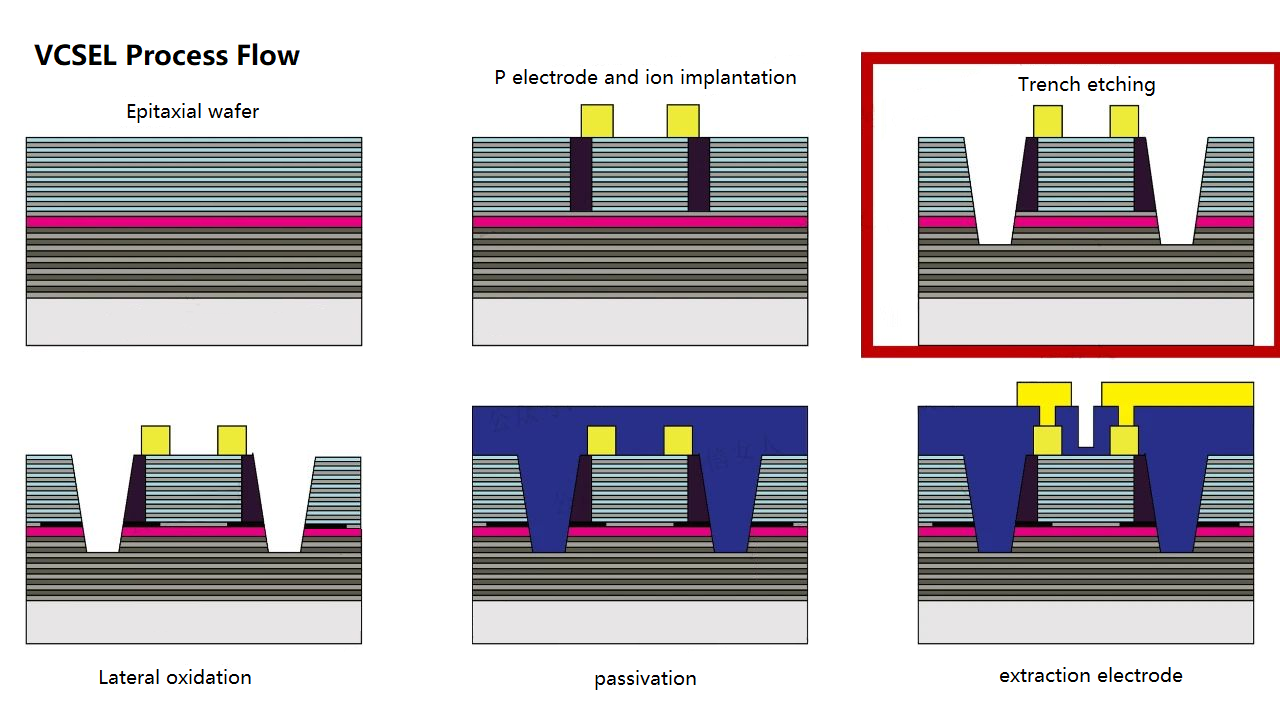
VCSEL process flow
Lift off those airtight coatings on the surface, and you will see an etched groove. This groove is oxidized through the side to form an internal current input and emit light. If the light structure is reduced to a diameter of 1.xμm, it can be limited to “single mode” in spatial dimension. However, there is also a DBR layer in this hole, a resonant cavity, which needs to control the reflection of light and interfere amplification after resonance. The DBR layer needs dozens of layers. The smaller the island, the more likely it is to achieve the single mode, but it will lead to hidden dangers in the reliability of the resonant cavity. In the 50G and 100G VCSELs seen this year, the diameter of the confinement hole is about 5~6μm.
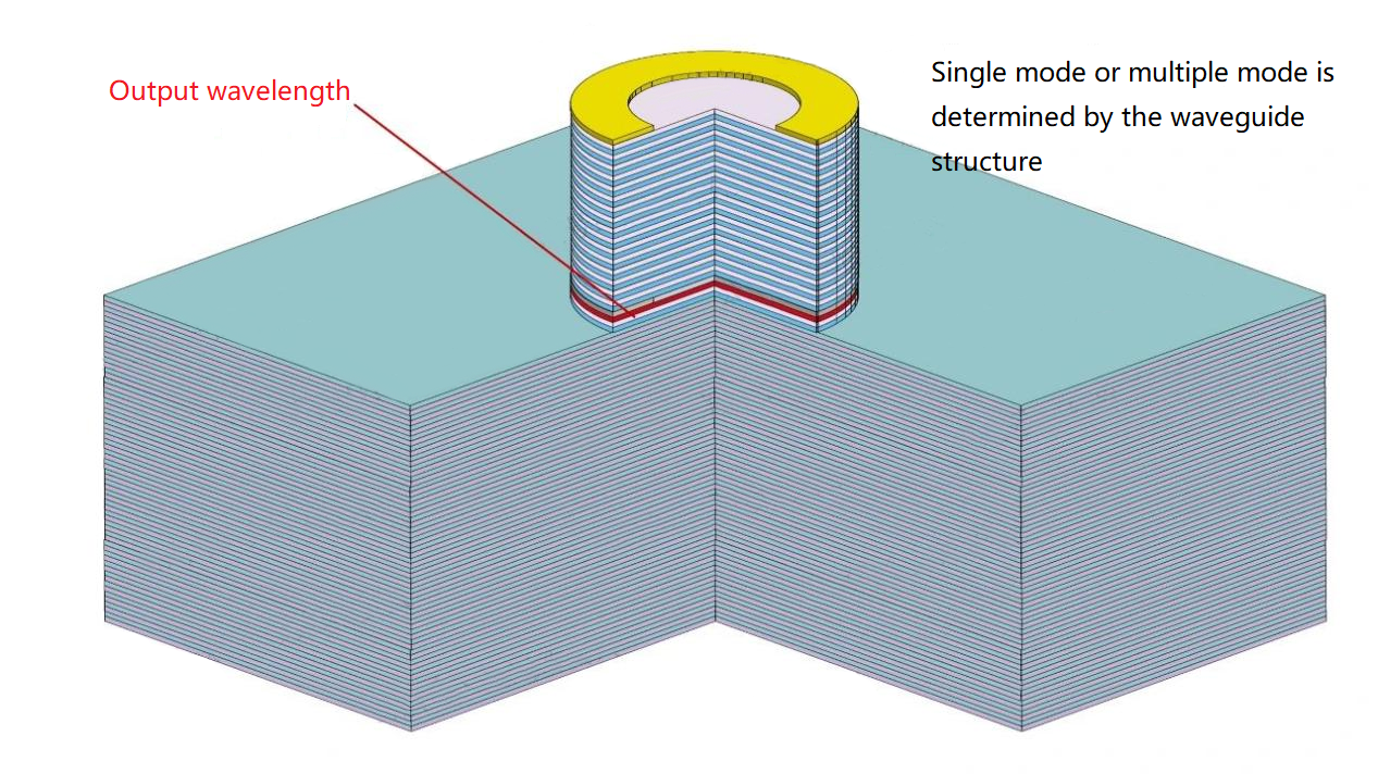
Single mode or multiple mode is determined by the waveguide structure
The numerous methods mentioned above shows that VCSEL can be single mode in theory, and in the current multi-mode state, there are also many auxiliary processing modes to achieve single mode. However, the industry expectations are low-cost and large-scale manufacturing, so multimode is the industry’s choice.
People prefer to choose 50G VCSEL or 100G VCSEL at present. If we want to maintain single mode at various temperatures, different currents, and different working hours, we will face high pressure in products.
All in all, technically, single or multi-mode and wavelength are independently designed. The transverse mode is generally limited by the spatial structure of the pinhole diffraction. The wavelength is jointly affected by the gain layer and the resonant cavity, with the gain material as the main reason.
In terms of application, the industry has wavelength and mode requirements. Single-mode InP lasers, especially those with distances above 500 meters and within thousands of kilometers have performance advantages, but InP edge-emitting lasers do not have the cost advantage. As for the multi-mode VCSEL laser, it boasts low cost, while with worse performance compared to the single mode one. It can be used for a distance of 180 meters. It also doesn’t have advantage in wavelength.
Lidar has requirements on the wavelength, while some test schemes have no requirements on the transverse mode, so a long-wavelength multi-mode design has emerged. What we just mentioned is the communication for mainstream solid-core glass optical fiber. When it comes to a hollow-core optical fiber, there are requirements for the mode, but there is less restriction on the wavelength, so there comes the short-wavelength single-mode solution, such as 1060nm single-mode lasers, using GaAs material system for edge emission.
