Though there is not much progress on DFB in the industry, it does not stop further research on DFB. Today, we will introduce several latest studies on DFB:
- Surface-emitting DFB is mainly used for short-distance applications. It boasts single mode and easy coupling.
HUST has developed single mode surface-emitting DFB laser with a surface grating. By introducing a phase shift in the etched area, the output power of the laser reaches 2mW, the SMSR is 46dB, the grating coupling coefficient is 560 cm-1, and the slope efficiency is 0.3W/A.
Vertical-cavity surface-emitting lasers (VCSELs) are widely used in short-link networks exceeding hundreds of meters. Hyperscale data centers prefer single mode transmission systems with higher bandwidth and longer-distance transmission capabilities. The oxide aperture size required for single mode VCSELs is typically less than 5 μm, which poses manufacturing and reliability challenges. It proposes a single mode surface-emitting DFB laser structure, which uses a horizontal cavity instead of a vertical cavity to achieve surface emission. The laser optical feedback uses a first-order grating, and the surface emission is achieved using a second-order grating.
In order to obtain a high grating coupling coefficient, a shallow ridge waveguide structure and a shallowly etched surface grating filled with SOG are used.
In order to reduce resistance and photon absorption losses, it adopts an N-I-P structure, and a tunnel junction is introduced into the substrate to achieve current injection.
In the area under the ridge waveguide, large-area rectangular oxide holes are designed to limit current injection.
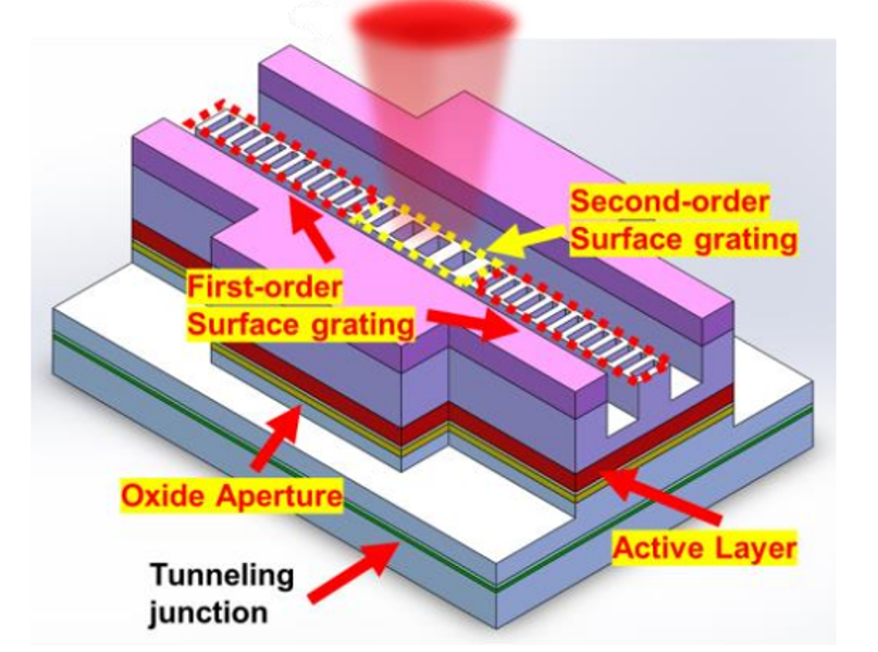
The three-dimensional diagram of the single-mode surface-emitting DFB laser
To concentrate the photons at the center of the resonant cavity (at the second-order grating) to improve the diffraction output, a λ/4 phase shift position is designed at the second-order grating. The position of the λ/4 phase shift at the second-order grating will affect the diffraction characteristics of the second-order grating, and two structures are designed as shown in the figure. In order to obtain a higher grating coupling coefficient, the AlGaAs upper cladding is optimized and SOG filling grating is used. The active region length of the laser is 40 μm, and the two DBR mirrors are 80 μm.
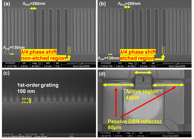
The SEM pictures
When the number of second-order gratings is 5, the slope efficiency of the λ/4 phase-shifted laser in the unetched area of the second-order grating is about 0.06 W/A, while the slope efficiency of the λ/4 phase-shifted laser in the etched area is about 0.2 W/A.
When the number of second-order gratings is 9, the slope efficiency of the λ/4 phase-shifted laser in the second-order grating etched area is about 0.3 W/A. The threshold current of the laser is about 2.1 mA.
When bottom DBR reflectors are used in the future, the output power and slope efficiency will be doubled. When the injection current is greater than 3mA, the laser has a stable single mode output at 25°C and the SMSR is greater than 46 dB.
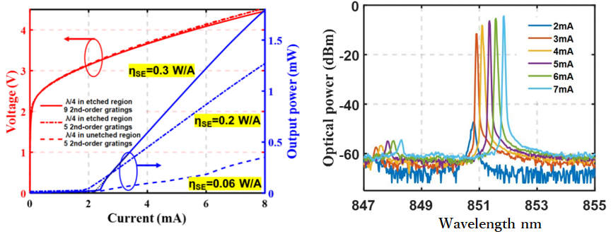
LIV curves of the fabricated lasers and Output spectra versus injection current
- Further utilize the PPR effect to increase the DML bandwidth to 53GHz. This feature is optimized to ensure PPR stability, and the DFB array can be used for short-distance LAN-WDM.
NTT proposed the first DML array that exploits the photon-photon resonance (PPR) effect in wavelength division multiplexing (WDM) short-reach interconnects. An 8-channel LAN-WDM thin-film laser array on SiO2/Si transmits at 106 GBaud NRZ over 2 km with an energy consumption of ~154 fJ/bit.
The DML bandwidth is increased by introducing the PPR effect in the membrane cavity design. The difficulty lies in the stability of PPR. The DBR reflector is 200 μm long and connected to the 80 μm long DFB to achieve single mode operation through filtering. By optimizing the grating design, the structure has sufficient PPR stability over multiple channels of the laser array.
Change the Bragg wavelengths of all three sections of each 8λ channel in the array simultaneously and get a 5nm wavelength grid suitable for LAN-WDM. This is achieved by adjusting the grating spacing of all sections in each channel. The maximum fiber-coupled output power of all lasers is greater than 0 dBm, and the wavelength spacing is about 5 nm. The kinks in the LI diagram are caused by side mode hopping and DBR filtering effects.
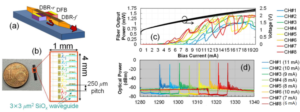
Laser array structure (a) & (b), and static characteristics: (c) L-l-V and (d) lasing spectra
At 50°C and 7 to 12.1 mA bias current, the 6 dB bandwidth of all channels is greater than 53.5 GHz, and the PPR frequency is between 40 and 50 GHz. In the response of channel #8, two PPR frequencies can be seen, which are caused by the relatively high grating coupling coefficient used (at 600~750 cm-1).
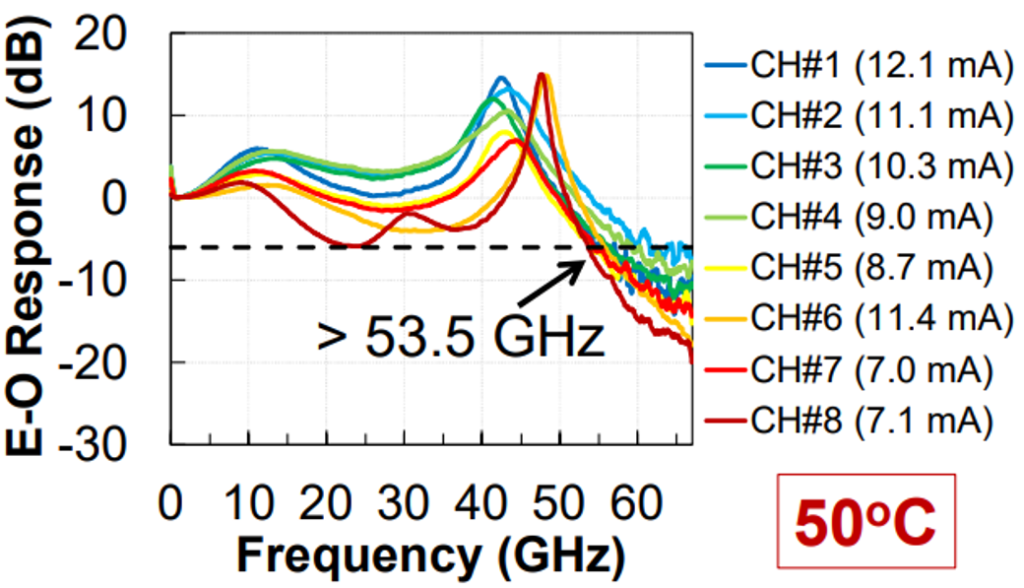
E-O responses at 50℃
The laser is driven directly at 1~1.3 Vpp. The bit error rate of all channels can achieve below 6.25% header hard decision forward error correction (HD FEC) at 50° back-to-back (BTB) and over 2km transmission, with a net data rate of 99.375 Gbps per lambda and a total data rate of 795 Gbps. The performance difference in the BTB and 2 km cases is negligible.
- High-power DFB light source can be used for silicon photonic light source. Its main feature is the SCOW structure, which has greater power than similar ones and supports full-temperature operation.
III-VLab designs high-power DFB lasers and MOPAs using buried-ridge slab-coupled optical waveguides. The device is based on SCOW and adopts semi-insulating buried heterostructure technology (SIBH). The MQW consists of a GaInAsP compressive strain well and an AlGaInAsP quinary tensile strain barrier.
The DFB laser is 2 mm long. The laser part of the MOPA is 1.5 mm long, the SOA part is 2.5 mm long, and there is a 500um Bessel bend at the output, with a waveguide angle of 7°.
When DFB is at 1A, the maximum output power is 148 mW at 85°C and 333 mW at 25°C. The thermal resistance for a 2 mm long DFB laser is about 6.6 K/W. Starting at 300 mA, the maximum value of RIN is less than -160 dB/Hz. The minimum linewidth is less than 30 kHz at 200 mA. When the current is larger, the linewidth increases due to the hole burning along the longitudinal space of the DFB laser cavity, but remains below 80 kHz at 900 mA.
When the DFB current is set to 1 A, the output power is approximately 300 mW. The MOPA achieves a maximum output power greater than 480 mW at an SOA current of about 1.65 A. The structure has good thermal performance and the wavelength of the laser part is very stable when the SOA current is up to 1.5 A.
- For quantum dot lasers, most of the research is based on FP lasers, and the DFB performance produced is very poor. However, the DFB power and line width demonstrated by Innolume this time are not bad.
Innolume reported that the linewidth FWHM of O-band InAs/GaAs QD DFB lasers is as low as 92 kHz (Lorentz part as low as 6 kHz). The laser output power after packaging reaches 90mW@600mA. The laser thermal resistance is estimated to be 28 (K/W)·mm.
The main improvements are:
1)The laser cavity was extended to 4 mm to increase the cavity q-factor.
2)The grating design increases the grating coupling coefficient kL to 2 and is optimized to reduce the peak detuning of the gain medium at 25°C.
3)By widening the asymmetric waveguide, the fast axis divergence angle is reduced from 35 degrees to 28 degrees.
Two methods are used to test the corresponding line width under high and low power conditions.
At low power of 10 mW, the linewidths were measured using a self-heterodyne technique and were found to be 30 kHz and 75 kHz for the Lorentzian and Gaussian lines, respectively.
At high powers which cannot be reliably described by the Voigt function, the optical phase-frequency noise is measured directly, since the laser line profile is determined by the frequency noise spectrum. When the optical power increases from 10mw to 75mw, the formula shows that the Lorentz linewidth decreases from 30khz to 6khz.
