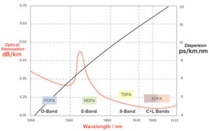
In optical transmission, we often explore the expansion of the spectrum in the hope of increasing the capacity of optical transmission systems. The largest spectral ranges that are currently commercially available are the C and L bands, and the extended C++ and L++ bands, which can reach a maximum spectral width of 12 THz. As shown in the figure, these bands are basically in the minimum range of fiber attenuation.
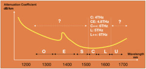
Because in these optical fiber attenuations of the most minor place, can make our network cost the lowest, or more accurately, the construction cost of the optical layer is optimal. (Components of fiber optic loss and how to reduce it?)
In addition to the cost of wave combining and distributing/WSS, solutions for the optical layer usually focus on the following aspects:
- Cost of amplifiers
- Cost of relay regeneration
When the transmission distance is over 100km, we use EDFA to compensate for the attenuation caused by the fiber. However, when the attenuation of the fiber optic line exceeds this range, we usually use Raman amplifiers to increase the transmission capacity for longer distances. Raman has a higher amplification capacity and can also introduce less noise. However, Raman is more expensive, and its Opex for opening and maintenance is much higher than ordinary EDFA.

For relay regeneration, if the fiber attenuation is too much, we need to set more amplifiers between stations at the same distance, and the accumulation of amplified spontaneous emission (ASE) noise generated by the amplifiers. This also increases the number of spans, so that the wavelengths need to penetrate more wave combining and distributing/WSS veneers. As a result, the performance of OSNR is reduced, so more relay boards should be added to realize 3R and other functions at the design stage, ultimately resulting in excessive Capex.
Therefore, in general, we will try to choose the least attenuated fiber band when choosing the band to carry the signals. This is why the current mainstream manufacturers choose to do it in the C / L band.
So what other ranges of the spectrum can we develop for light transmission besides C and L? In the picture at the beginning of the article, in addition to C and L, there are longer wavelength U-band and shorter wavelength O/E/S-band.
For the longer wavelength U-band. It faces the problem that bending loss has a greater effect on longer wavelengths. In the figure below, the optical mode becomes smaller and lossier with increasing wavelength at the same bending radius.
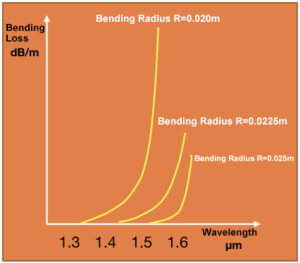
Of course, it is not infeasible to transmit in U-band, which requires us to develop optical fibers with better bending resistance, such as photonic crystal fibers. It just doesn’t quite fit at the current stage with the mainstream trend and universal application of optical fibers.
In this case, can we choose in the shorter wavelength range such as O/E/S?
Let’s take a look at the fiber transmission performance metrics within these wave bands, which are also commonly used to evaluate optical systems.
- Attenuation
- Nonlinear Effects
For fiber attenuation, due to water-peak loss, Rayleigh scattering and the ultraviolet loss, the fiber attenuation in these individual bands is much higher than in the C/L band range, thus increasing the need for amplifiers to solve the fiber attenuation. Amplification techniques based on alternative rare earth elements or extended Raman amplifiers have also been experimentally validated, and the following figure shows the types of amplifiers with different elements.
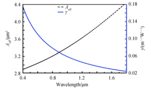
Fiber nonlinear effects are inversely proportional to wavelength, the shorter the wavelength, the more serious the nonlinearity, so the nonlinear effects will be more serious for wavelengths below C-band. Meanwhile, one indicator related to fiber nonlinearity is the module effective area, the larger the module area, the stronger the resistance to nonlinearity. For more information about nonlinearity, please refer to the article: What is the nonlinear effect in optical fiber?
We can understand the above passage well by the following figure (about the variation of the mode field area and nonlinear coefficient with wavelength). The blue line γ is the nonlinear coefficient of the fiber, and the black line Aeff is the effective mode field area. As the wavelength decreases, the mode field area decreases and the resistance to nonlinearity decreases, while the nonlinear coefficient increases, resulting in a more severe nonlinear effect from the fiber.
In addition, the dispersion brought by the fiber and the effect on different wavelengths is also a factor in the system nonlinearity index. At 100G and super 100G rates, the problem of dispersion has been well solved by electric domain compensation.
Therefore, for different ranges of wavelengths, we are not afraid of having dispersion but are concerned about too little or even no dispersion. Because smaller dispersion or zero dispersion will bring very serious Kerr effect (nonlinear effect). The following figure shows the dispersion variation for different fiber types.
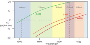
It can be seen that the current dispersion value of the commonly used fiber G.652 is floating around 0 in O-band and G.655 is floating around 0 in S-band. For G.653 fiber, its dispersion is around 0 in the C-band, which is one of the reasons why G.653 fiber (even G.655 fiber has small dispersion here) is not commonly used in later 100G and above systems.
Above we only briefly mentioned the attenuation and nonlinearity of the development of shorter wavelengths must be considered, the commercial cost of commercial maturity after the technology verification is also an important consideration.
Back to the beginning, in fact, the exploitation of shorter wavelengths is already being implemented, for example, the C++ and L++ bands are actually extended to utilize about 10nm of spectrum in the S and L bands. It is believed that in the near future, spectrum resources beyond C and L will be exploited for optical transmission.
Table of Contents
ToggleRelated Products:
-
 SFP-DW10G54-80C 10G DWDM SFP+ C54 100GHz 1534.25nm 80km LC SMF DDM Transceiver Module
$175.00
-
 SFP-DW10G35-100C 10G DWDM SFP+ C35 100GHz 1549.32nm 100km LC SMF DDM Transceiver Module
$235.00
-
 SFP28-DW25G33-10C 25G DWDM SFP28 C33 100GHz 1550.92nm 10km LC SMF DDM Transceiver Module
$265.00
-
 SFP28-DW25G31-20C 25G SFP28 DWDM C31 100GHz 20KM 1552.52nm LC SMF DDM Transceiver Module
$600.00
-
 SFP28-DW25G29-40C 25G SFP28 DWDM C29 100GHz ER 40KM 1554.13nm LC SMF DDM Transceiver Module
$750.00
-
 Q28-2DW5758-80C 100G DWDM QSFP28 PAM4 80km C57 C58 100GHz CS DDM Optical Transceiver
$1600.00
-
 Q28-DW100G37-80C Compatible 100G DWDM QSFP28 PAM4 Single Wave C37 1547.72nm 100GHz LC 80km DDM Optical Transceiver Module
$1900.00
-
 EDFA 40/80 Channels DWDM C-Band Optical Pre-Amplifier Maximal Output Power +16dBm Gain 25dB Saturated Optical Power -9dBm
$1139.00
-
 EDFA 40/80 Channels DWDM C-Band Optical Line Amplifier Maximal Output Power +16dBm Gain 25dB Saturated Optical Power -9dBm
$1139.00
-
 DCM 80km DCF-based Passive Dispersion Compensation Module, 8.0dB Low Loss, LC/UPC Connector
$929.00

