
During the use of optical transceiver modules, various problems will inevitably occur. This article summarizes two common issues with optical modules and the corresponding solutions.
The main reasons and solutions for optical module failure
| Factor | Description |
|---|---|
| Wavelength | Prohibit the connection of optical modules of different wavelengths. Due to the different transmission loss and dispersion in optical fiber, the transmission distance corresponding to different wavelengths at the same rate is different, so it is necessary to choose optical modules of the same wavelength when connecting. |
| Transmission distance | The interface specifications of optical modules vary with distance, and the long-distance optical modules are expensive. Therefore, an optical attenuator must be added to connect a long-distance optical module to a short-distance optical module. To avoid burning out the optical module, it is recommended that the distance of the optical module should not be smaller than the length of the optical fiber. |
| Rate | The nominal rate of the optical module must be consistent with the actual link rate. High-speed signals are not allowed to run on a low-rate optical module. The nominal rate of the optical module must be greater than that of the interface. |
| Mode | Optical fibers and optical modules must be paired. That is, single-mode optical modules use single-mode optical fibers, and multi-mode optical modules use multi-mode optical fibers. |
Failure phenomenon
Two optical interfaces through the fiber docking, the local port Down, optical module docking does not work.
Possible causes
- The optical transceiver used is not compatible with the equipment
- The optical module and fiber do not match
- The port is shutdown
- The transmitting optical power is too low or too high
- Receiving optical power is too low or too high
- The optical transceiver mismatch between the two ends of the docking
- Port configuration does not match the module type
Troubleshooting Procedure
- Check whether the optical module on the Down port is compatible with the device. Incompatibility between the optical module and the device is manifested as follows:
- The module is not recognized by the device, the module is inserted into the device and does not respond, and the transceiver information is not tested.
- If a module is inserted, the device displays unsupported information and alarm information such as not supported, unknown, and No qualified.
- Insert a transceiver, checking whether the device status indicator is abnormal or the port is disconnected.
- The module connects, but the information is abnormally displayed. For example, information such as unknown sfp is displayed.
The reliability of an incompatible optical module cannot be ensured. As a result, the port may fail to UP.
- Check whether the optical module matches the optical fiber
- The general wavelength of a single-mode optical module is 1310nm and 1550nm. The corresponding single-mode optical fiber is yellow.
- The wavelength of a multi-mode optical module is 850nm. The corresponding multi-mode fiber is usually orange, aqua blue, or rose red.
- Take the HW switch as an example, execute the command display interface transceiver to check whether there is alarm information of the optical module under “Alarminformation”. If there is a LOS Alarm alarm, it means that no signal is sent from the other side. Execute the command display interface in interface mode to see if the ports at both ends are shutdown, and if the ports are shutdown, execute undo shutdown operation.
- Execute the command display interface transceiver verbose to view the diagnostic information of the optical module and check whether the optical module has alarm information about transmitting or receiving optical power.
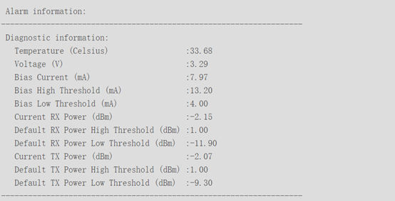
In the diagnostic information of the optical transceiver, you can check the current transmit and receive optical power values, as well as the default maximum and minimum power values.
- If the received power is low (RxPower Low), the signal received at this end is too low. It may appear that the port is not UP or there is a drop in message sending and receiving after UP. At this point, please first check whether the transmission distance is too far, beyond the transmission distance of the opposite end of the optical module. Then check whether there is damage to the optical transceiver and fiber.
- If the received power is high (RxPower High), the signal received at this end is too high. The possible reason is that the optical module at the opposite end is a long-range optical module, and the actual transmission distance is too short, resulting in the signal not being attenuated. At this time, light attenuation should be added to the optical module at the opposite end to protect the optical module from this end.
- If the transmit power is low (TxPower Low), it means that the transmit signal of the optical transceiver at this end is bad or the optical module itself is faulty. It may lead to low receiving power at the other end, and cause the port not to be UP or UP after the message sending and receiving with discard.
- If the transmit power is high (TxPower High), it means that the transmit signal of the optical module at this end is too strong. It may lead to high receiving power at the opposite end, and cause the optical module at the opposite end to burn out due to continuous high receiving power. The possible cause is the failure of the optical module at this end, and it is recommended to replace the optical module
Therefore, after the port is inserted into the optical transceiver and connected successfully, the alarm information on the transmit or receive optical power should be checked to avoid abnormal traffic or optical module status caused by low or high power.
- If there are no alarms at both ends, and the port is not UP, please first intercept the optical module details and obtain the relevant logs. Then try to replace the fiber or optical module to see if it can UP normally. if it can, the original fiber or optical module itself has problems, please replace the new fiber or optical module. If it still can’t be UP, please contact the technical support staff.
The main causes of optical module failure and protective measures
The optical transceiver must be operated in a standardized way. Any improper action can cause hidden damage or permanent failure.
The main causes of optical Transceiver failure
The main causes of optical module failure are deterioration of optical module performance due to ESD damage and optical link failure due to optical port contamination and damage. The main causes of optical port contamination and damage are:
- The optical port of the optical transceiver is exposed, and the optical port is contaminated by the entry of dust.
- The end face of the fiber optic connector used has been contaminated, and the optical port of the optical module is secondary contaminated.
- The end face of the optical connector with pigtail is misused, such as end face scratches, etc.
- The use of poor-quality fiber optic connectors.
Effective protection against optical transceiver failure is mainly divided into two methods: ESD protection and physical protection.
ESD Protection
ESD damage is a major problem that causes deterioration of optical device performance and even loss of device optoelectronic function. In addition, ESD damaged optical devices are not easy to test and screen, and it is difficult to locate them quickly if they fail.
Operating instructions
- Optical transceivers must be in anti-static packaging during transportation and transfer before use, and must not be removed or placed at will.
- Before contacting the optical transceiver, anti-static gloves and anti-static bracelets must be worn, and anti-static measures must be taken when installing optical devices (including optical modules).
- Test equipment or application equipment must have a good grounding wire.
Physical protection
The laser inside the optical transceiver and the temperature control circuit (TEC) are more fragile and easily break or fall off after receiving an impact, so physical protection should be paid attention to both during transportation and use.
The optical port can be lightly wiped with a cleaning swab, but a non-special cleaning swab may cause damage to the optical port, and excessive force when using the swab may cause the metal in the swab to scratch the ceramic end surface.
The insertion and extraction of the optical module are designed to simulate manual operation, and the thrust and pull forces are also designed to simulate manual operation, and no apparatus should be used during installation and removal.
Operation instructions
- When applying the optical transceiver, pay attention to holding it gently and preventing it from falling.
- When inserting the optical module, push it in by hand and do not use other metal tools to do so; when pulling it out, open the pull ring to the unlocked position before pulling the ring, and do not use other metal tools to do so.
- Use special cleaning cotton swabs when cleaning the optical port, and cannot use other metal substances to insert into the optical port.