The word optical engine has been discussed more and more frequently. This article will roughly distinguish between optical transceivers and optical engines. The fundamental purpose and core function of the optical transceiver are to convert the electrical signals and the optical signals.
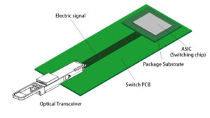
After the optical transceiver is independent, its industrial scale is getting bigger and bigger. To reduce the cost of the industry, it is necessary to form some specific standardized systems from the ideas of different manufacturers’ designs, so that products from different manufacturers can be compatible and interoperable with each other.
Thanks to large-scale interoperability in the industry, the cost of optical transceivers is getting lower. There are specific standards for the shape, the electrical interface, and the optical interface of the optical transceiver respectively. There are also detailed specification standards for internal optical signals/electrical signals. The digital diagnostic software interface also has a specific standard system.
When the optical modules are manufactured in industrial chains, they will become “universal”. The same type of laser chips, electrical chips, housings, and so on, are much cheaper than customized ones. For transceiver manufacturers, most of the design and production steps are the same when they sell the transceivers to several customers at relatively low costs. For Party A buys optical transceivers, it can choose any supplier providing quality and cheap products.
When optical transceivers meet the key factor of interoperability, the entire industry chain actually benefits from it. The functions of the optical transceiver include the core photoelectric conversion and peripheral auxiliary. Peripheral assistance is to reduce the industrial cost of large-scale manufacturing, which is similar to the rule we buy screws for general purposes. The advantage of general service is to save time, effort, and money.
What is an optical engine? The word engine is often seen in cars, which is the core part of a car. A car also needs to be equipped with auxiliary parts such as seats, windows, and doors to form a product based on the core function of the engine.
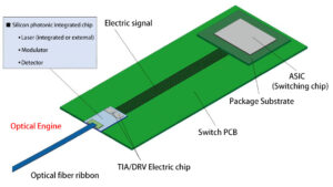
The optical engine is the main part of the optical transceiver for realizing photoelectric signal conversion. Especially after the large-scale application of silicon photonics integration, the main units of electro-optical conversion and photoelectric conversion are integrated. Unlike traditional optical transceiver components, which are very scattered, the assembly of optical engines is as compact as the assembly of optical transceivers. In the silicon photonics integration, the electrical chip and the silicon-photonics integrated chip, connected with the optical fiber, form a complete “engine” for signal conversion.
This engine ignores those parts of interoperability, does not specify the optical interface, electrical interface, shape, etc., and only pays attention to the most central signal conversion. After the optical transceiver manufacturer takes the optical engine back, it is equipped with the optical interface, electrical interface, and housing, and the interoperability part of the optical transceiver in the later stage is basically completed.
Let’s talk about what is OBO and CPO next. These two are different from hot plugging. They refer to the relative position of the optical transceiver (or optical engine) and the switching chip.
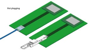
Hot plugging, optical transceiver, or optical engine, located on the front panel of the system for easy replacement and quick maintenance. Because the laser in the optical transceiver is the diode with the highest failure rate in the entire optical fiber communication system, once it is broken, a new transceiver needs to be replaced in the shortest time. It seems to be easier to directly replace the laser chip, but the chip is as thin as a hair, and the parameters of each laser chip are different, so it can be barely done in reality.
Hot swapping reduces maintenance costs, but the problem is that the optical transceiver and optical engine on the front panel are far away from the switching chip, and the electrical signals are routed in the PCB for a long time. In the current high-speed 400G/800G optical transceivers, people who do circuit design and PCB layout are very clear about how seriously the signal is degraded if the PCB wiring is too long.
In order to alleviate the degradation of the high-speed signal caused by the long electrical signal of the PCB, one of the solutions is to place the engine close to the switching chip, which is onboard optics(OBO). The optical engine is moved to the middle of the PCB board from outside the board(front panel). The purpose of the OBO is to reduce the connection distance of the electrical signals.
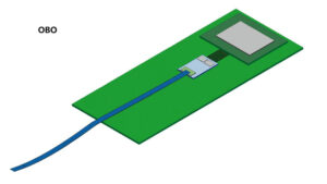
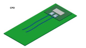
CPO, co-packaged optics, means that the optical engine is directly moved to the packaging substrate of the switching chip, and the “co-packaged” form factor completely shortens the electrical connection distance between the optical engine and the switching chip to the limit.
