Currently, the need for efficiency and high-capacity data transmission is more important than ever due to the rapid development of technology. The core of modern fiber optic communication systems and supporting infrastructure for high-speed data networks are multi-fiber push-on (MPO) connectors. This ultimate guide gives a deep dive into MPO fiber by looking at its design, how it works, and its uses. By understanding the intricacies and benefits associated with MPO connectors, industry experts can employ this technology to enhance their network performance as well as scalability. Whether you are an engineer, technician, or just a curious person in this field, this piece seeks to educate you about key things that will enable you to navigate through the world of multi-fiber optic cable connectors easily.
What is MPO Fiber and How Does it Work?
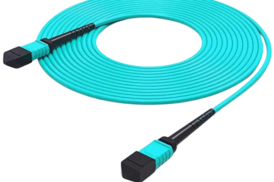
Defining MPO Fiber Connectors
MPO fiber connectors are a kind of high-density fiber optic connectors made to connect multiple optical fibers together through one port. These types of connections usually have rectangular ferrules with 12 – 72 fibers, which are precisely aligned to ensure low insertion loss and proper functioning signal integrity. This means they can be easily deployed and expanded, making them ideal in data centers, telecommunication networks, and other high bandwidth applications. The MPO connector has a standardized design that follows strict industry standards, ensuring compatibility, consistency, and functional reliability across different network devices and infrastructure.
The Role of MPO in Optical Networks
Highly dense fiber optic cables can be well-maintained in optical networks by MPO connectors to simplify work. It is crucial for these connectors to support high-speed data transmission, minimize the complexity of network infrastructure as well as guarantee strong connectivity. Thus, here are some technical parameters that show their significance:
- High Fiber Count: In this case, multiple fiber connections are brought together to one efficient interface through a MPO connector hence enabling 12-72 fibers.
- Insertion Loss: This can be within a range of 0.1 dB and 0.35 dB which could depend on the type of the MPO connector either standard or low-loss thereby making sure that signal degradation is minimal.
- Return Loss: In terms of high speed data applications, MPO connectors provide excellent performance with return loss values above 20 dB (Standard Connectors) and above 60 dB (Angled Physical Contact).
- Polarity Management: Aspects such as system interoperability are reliant on signal routing’s maintenance through certain polarity management schemes provided by these types of connectors, namely types A, B, and C.
- Compatibility: For instance, TIA-604-5 and IEC61754-7 adherence ensures wider compatibility for other vendors’ equipment and infrastructures.
Therefore, through minimizing loss and maximizing throughput with excellent return loss while having scalable communication links, modern optical networks cannot do without MPO connectors which enable high capacity backbones.
Components of MPO Fiber Optic Cables
MPO (Multi-fiber Push On) fiber optic cables comprise several important parts that guarantee their high performance and dependability.
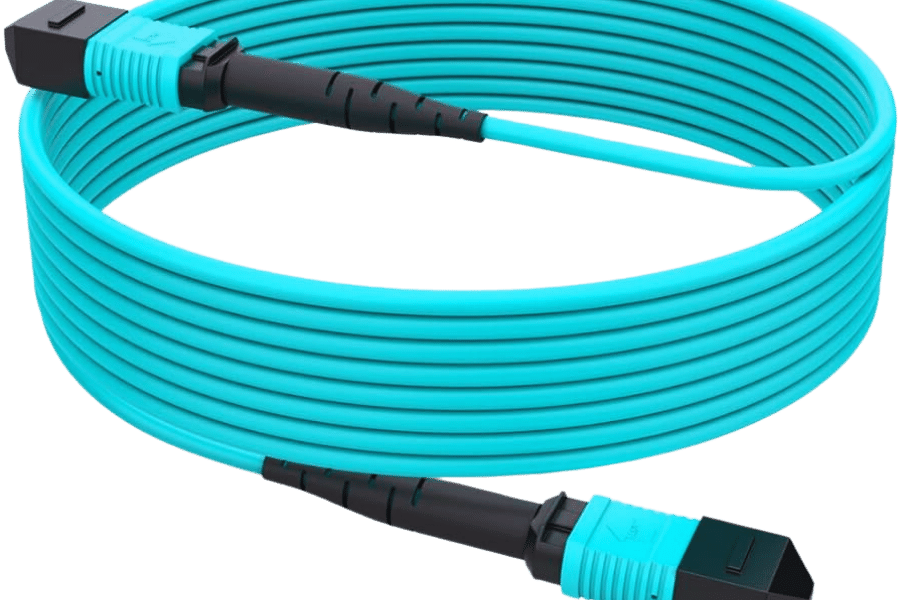
- MPO Connector: The MPO connector is the cable’s core, which manages high-density fiber counts. It is designed as a male or female type with correctly mating alignment pins.
- Fiber Optic Cable: This ribbon-based fiber optic cable can be of different types such as single-mode or multi-mode supporting dense packing of fibers. Such cables have tough covering to resist mechanical damage and electromagnetic interference that may impair data transmission.
- Ferrule :It is made from precise ceramics that aligns and holds the fibers in place in the connector. The low insertion loss and return loss are guaranteed by this component.
- Housing and Boots: While housing serves as structural support for cable, boots act as strain relief, protecting the optical fibers from bending or being affected by other mechanical forces during installation or servicing.
- Polarity Management System : This unit ensures the right signal transmission route so that potential cross-connections can be avoided. Polarity types are key to maintaining a defined signal flow.
These components jointly ensure modern data centers, telecommunications networks, etc., work at peak efficiency and adapt well to changes, thus facilitating fast data transfer rates between computer systems and seamless connections between devices.
What are the Different Types of MPO Cables?
MTP® vs MPO: Understanding the Differences
While MTP® (Mechanical Transfer Pull-off) and MPO (Multi-Fiber Push On) connectors are often used interchangeably, there are differentiating factors that separate the two. The MTP® connector is a trademark of US Conec, and it has superior performance and more features than the standard MPO connector. The manufacturing precision of the MTP® connectors is higher, which gives them better optical and mechanical performances because of their narrower tolerances and better loss properties. Moreover, these connectors possess some advanced qualities such as a detachable housing for easy repolishing, floating ferrule for enhanced physical contact, and robust strain relief design. Conversely, typical MPO connectors may not be as versatile or effective as an equivalent number of cables made from OM3 fiber—making MTP® connectors preferred in high-performance applications such as data centers or telecommunication networks.
12 Fiber vs 24 Fiber MPO Cables
It is necessary to consider the technical parameters of each of these cables and the environment in which you network.
12 Fiber MPO Cables:
- Applications: Typically used in Duplex (10G, 40G, 100G) applications.
- Connector: Contains 12 fibers in a row of one.
- Bandwidth: It supports up to 100G Ethernet.
- Usage: For short-distance high-density networks, data centers requiring modularity and ease of deployment are given priority here.
24 Fiber MPO Cables:
- Applications: Commonly used in high-density (40G and 100G with parallel optics) applications.
- Connector: Has two rows of twelve fibers, each totaling twenty-four fibers.
- Bandwidth: This can achieve up to 200 G Ethernet support.
- Usage: Data centers, more bandwidth requiring network designs as well as higher port densities over the same physical interface call for such cables.
Technical Parameters:
Insertion Loss:
- 12 Fiber: Typically ≤0.35 dB (with elite versions achieving ≤0.15).
- 24 Fiber: Typically ≤0.35 dB per row.
Return Loss:
- 12 Fiber:≥60dB.
- 24 Fiber:≥60dB per row.
- Operating Temperature : The usual scope for both kinds is between -40°C and +85°C.
- Durability: An MPO connector has a minimum lifespan of about five hundred insertions regardless of whether it has twelve or twenty-four fiber counts.
By considering these parameters and their respective uses, telecom infrastructure planners can choose between deploying either twelve-fiber or twenty-four-fiber MPO cables based on their specific needs for telecommunication infrastructure and data center environments.
Choosing Between Singlemode and Multimode Fiber Options
In the choice between singlemode and multimode fiber optic cables to be used for your network infrastructure, it is important to know what your specification is.
Singlemode Fiber: This type of fiber has a smaller core (typically 8-10 microns) and carries light directly down the middle. Because of this direct transmission, single mode fiber cables can support higher bandwidths and longer distances, often in excess of 10km for example. It best serves long haul telecommunications, metropolises and campus backbones where maximum distance and high bandwidth are critical. Lasers at the source of light make it expensive than multimode.
Multimode Fiber: On the other hand, multimode fiber has a larger core (50 or 62.5 microns), allowing different modes of light to travel within it. Data centers, LANs or on-premises installations such as those found in datacenters typically use this type of fiber since it is used over short distances. However, this kind uses cheaper LEDs or VCSELs as light sources. However, MMF supports shorter transmission distances usually up to 550 meters at speeds of 10 Gbps.
Key Differences:
Core Size:
- Singlemode: 8-10 microns.
- Multimode: 50 or 62.5 micrometers.
Bandwidth and Distance:
- Singlemode: Greater distance (over 10 km) and bandwidth.
- Multimode: Shorter distance (up to 550 meters for 10 Gbps).
Cost:
- Singlemode: Higher costs resulting from laser sources.
- Multimode: Lower costs through LED or VCSEL sources.
Considering the required distance that networks should cover, the economic implications involved, as well as how much data needs to be transmitted per unit time will enable you to choose wisely between SMF and MMF in terms of their fitness for use in your infrastructure.
How to Ensure Proper Polarity in MPO Fiber Systems?
Polarity Methods: Type A, B, and C Explained
To maintain signal integrity and avoid connection issues in MPO fiber systems, ensuring correct polarity is vital. The main polarity methods include Type A, Type B, and Type C.
Type A Polarity
This method is also known as “Straight Through” polarity. According to this method the fibers at one end of the MPO connector are aligned in the same sequence with those at the other end (1 to 1, 2 to 2…). This means that there is no crossing over of the fibers hence maintaining consistency throughout.
Type B Polarity
Another term for type B polarity is “Flipped” polarity. With this kind of arrangement, it means that the positions of fibers are reversed from those at either end of the MPO connector. For example, we can have position one fiber at one end connecting to at position twelve while position two connects to eleven and so forth. Essentially, all the fibers get flipped upside down with respect to their previous positions.
Type C Polarity
“Pairwise Flipped” or Type C Polarity implies that successive receptor pairs are exchanged. In this case, for instance, fiber pairs 1-2 get exchanged with 3-4, then 5-6, etcetera. As a result, each transmit line correctly mates with the duplex application receiver partner.
Each polarity method caters for different network configurations such as this thereby ensuring that transmit signals link properly with corresponding receive signals. Appropriate choice between them depends on specific application requirements and design objectives in a given MPO system design context.
Testing and Verifying MPO Cable Polarity
It is important to test and verify the polarity of MPO cables as it is one important step in its efficiency and error-free operation within a network. Specialized equipment is used during this process while following strict procedures for ensuring that the fibres are correctly aligned according to a chosen polarity method.
1. Visual Inspection
- To check the polarity of MPO cable, visual inspection is the first step. Look at each MPO connector for any obvious defects or dirt causing misalignment. In order to get accurate test results, all MPO connectors must be clean and free from contaminants.
2. Equipment
For testing and verifying MPO polarity, the following equipment is typically used:
- MPO Polarity Tester: Instrument specially designed to verify MPO cable polarities.
- Optical Time Domain Reflectometer (OTDR): Determines fiber length and detects faults along fiber length.
- MPO Light Source and Power Meter: Helps measure optical loss and ensure that fiber connections are still good.
- MPO Microscope: Checks the cleanliness of MPO connectors, among other conditions.
3. Test Procedures
Below are typical steps involved when testing for MPO cable polarity:
- Setup – Connecting MPO cables to either an MPO light source and power meter or an MPO polarity tester should follow what has been described in the user manual provided by the manufacturer of this equipment.
Verification:
- Type A: It should be ensured that fibers go straight through (i.e., 1-to-1, 2-to-2, etc.).
- Type B: Fibers are flipped (i.e., 1-to-12, 2-to-11, etc.).
- Type C: Adjacent pairs of fibers are swapped (i.e., 1-2-to-3-4, etc.).
- Measure Optical Loss – Use light source and power meter to measure insertion loss. Usual acceptable loss would normally be less than 0.75 dB per connection.
- Documentation – Record the test results, including the type of polarity, measured optical loss, and any issues found for future reference.
4. Technical Parameters
Ensure the following technical parameters are recorded and justified:
- Insertion Loss per Connection: < 0.75 dB.
- Return Loss: > 30 dB for multimode fibers and > 45 dB for single-mode fibers.
- Inspection Criteria: MPO connectors should not have visible defects or contaminants.
- Calibration: Ensure that all test equipment is calibrated as specified by the manufacturer.
Proper testing and verification of MPO cable polarity play an important role in the maintenance of high performance level and reliability in fiber optic networks. With such procedures, it is ensured that what has been implemented follows design specifications, which result in no connectivity problems within this system.
What are the Key Uses and Applications of MPO Fiber in Data Centers?
MPO for High-Density Data Centers
Because of their high density, MPO (Multi-Fiber Push On) connectors are important in data centers where they support high bandwidth applications as well as effective space utilization. With a single connector capable of accommodating up to 12 or 24 fibers, the physical footprint required for cabling infrastructure is reduced significantly. Due to this small size, it becomes easier for organizations to manage their cables and improve airflow, which is important for maintaining optimum thermal performance in dense data center installations. Additionally, MPO connectors form the basis for parallel optical transceivers necessary for high-speed data transmission that can handle speeds of 40G, 100G, etc, and above. These attributes make MPO solutions vital in contemporary data centers looking to meet increasing data needs economically.
Applications in 10G, 40G, and 100G Networks
MPO connectors are very flexible and significant to developing fast network infrastructures, more so in 10G, 40G, and 100G networks. Here is a brief description of how they are used in these networks and the required technical parameters:
10G Networks
- Technology: Usually, it adopts 10GBASE-SR transceivers.
- Connector Type: Duplex LC connectors are common for 10G, but MPO can be used for aggregation points.
- Fiber Type: People prefer OM3 or OM4 multimode fiber.
Technical Parameters:
- Maximum Distance: Up to 300 meters on OM3 fiber and up to 400 meters on OM4 fiber.
- Insertion Loss: <0.75 dB for MPO connectors.
40G Networks
- Technology: They use the following module types, such as QSFP+ SR4 (Serial Router) modules from Fiberstore Inc., which have four lanes of digital differential signals, each running at up to ten gigabits per second (Gb/s) over an MTP interface.
- Connector Type: Twelve fibers including four transmit channels, four receive channels and four unused ones form this type of connector’s construction.
- Fiber Type: For most short-reach applications, it should be OM3 or OM4 multimode fiber.
Technical Parameters:
- Maximum Distance: UP to about hundred meters on OM3 fiber and another fifty on the other one known as OM4 fiber.
- Insertion Loss:<0.35dB per connector with high-performance systems.
- Return Loss:>20dB.
100G Networks
- Technology: Uses such transceivers as frequently as possible – 100GBASE-SR10 or SR9 and CXP, for instance.
- Connector Type: The connector is composed of twenty-four fibers in case of SR10 and twelve fibers in case of SR4 respectively.
- Fiber Type: It is designed only for short reach applications using multimode fibre (OM4), while single-mode fibre is used for longer distance applications.
Technical Parameters:
- Maximum Distance: Up to 150 meters on OM4 fiber for SR4 and SR10 applications.
- Insertion Loss:<0.35 dB per connector.
- Return Loss:>20 dB @ multimode, >35 dB @ single mode.
The implementation of MPO technology in such networks does not only mean increased capacities of bandwidth but efficiency in cable management and space utilization. Adoption of the above technical standards provides data centers with the best performance and dependability in their high-speed network applications.
Advantages of MPO Fiber Breakout Cables
- Increased Scalability: MPO fiber breakout cables allow for easy scaling of network infrastructures through accommodating multiple connections within a single cable. It means that the expansion of data needs which occur as the company grows will not bring much disruption to the system.
- Improved Space Utilization: The high-density design of MPO breakout cables reduces significantly the physical space requirements for cabling. In data centers, where space is often at a premium, such efficient use of room is crucial.
- Simplified Cable Management: Through consolidating many connections into few cables, MPO breakout cables streamline cable management. As a result, installing and troubleshooting them becomes easier thereby minimizing errors and downtimes while also enhancing maintenance.
- High Performance and Reliability: These MPO fiber breakout cables adhere to strict performance guidelines by guaranteeing minimal rates of insertion and return losses. This implies that high-speed applications are characterized by high data transmission rates as well as reliable network performance.
- Cost Efficiency: The good design and simplified installation process associated with MPO breakout cables lead to lessened charges on labor and materials. Moreover, their ability to accommodate future network growth without further major investment enhances cost-effectiveness even more.
How do you connect and manage MPO fiber cables?
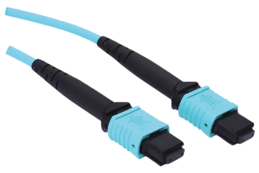
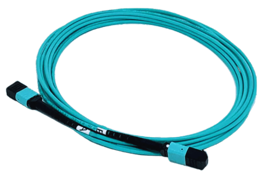
Installation Tips for MPO Trunk Cables
- Pre-Installation Planning: Plan the installation well. Determine network needs and designs as well as acquire the necessary equipment. This also includes knowing the length and types of cables accurately.
- Connector Inspection and Cleaning: Ensure that you inspect and clean MPO connectors every time before you connect them. Use a microscope to investigate end faces for debris or damage. To enhance performance, use things like lint-free wipes or specialized MPO cleaning kits.
- Proper Routing: Be careful when routing MPO trunk cables to avoid tight bends that can damage fibers due to excessive tension. Maintain cable integrity by observing manufacturers’ specifications on bend radius.
- Secure Connections: Insert MPO connectors into their respective adapters or transceivers firmly until it clicks, indicating a secure connection. Polarity and fiber alignment have to comply with the network design requirements.
- Labeling and Documentation: Each cable should be labeled clearly so that it can be easily identified in case of any issues requiring troubleshooting, among other things. The installation should be fully documented, including cable routes, connector types, and performance testing results.
- Performance Testing: When installation is completed, comprehensive performance tests must be carried out to check compliance with all the required standards on all links fitted. For example, insertion loss measurements, return loss measurements, overall link performance measurements etc.,
- Regular Maintenance: Schedule regular inspections and maintenance checks intended to sustain high-performance cabling systems. Additionally, this will help avoid any potential problems through periodic cleaning of connectors and testing.
These are some tips that will guarantee a successful installation process along with the long-term reliability of your network infrastructure’s MPO trunk cables.
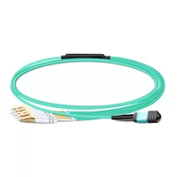
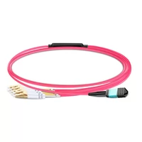
Managing MPO to LC Breakout Cables
Several important steps must be taken to ensure that MPO to LC breakout cables are managed efficiently and with the utmost reliability.
- Cable Selection: Opt for high-grade MPO to LC breakout cables that conform with the industry standards (e.g. ANSI/TIA-568-C.3) and rated as per your specific application environment. Ensure compatibility of fibre type, ferrule type and cable jacket material with your network requirements.
- Cleaning: Clean all MPO connectors along with LC connectors properly before installation. Dust or contaminants that could cause signal degradation can be wiped off using lint-free clothes or special cleaning tools.
- Installation and Routing: When installing the breakout cables, make sure they are not put into tight bends, twisted or pulled too hard, which may destroy their fibers. Follow the manufacturer’s specifications on minimum bend radius – usually 30mm for single-mode fiber and 10mm for multimode fiber.
- Secure Connections: Insert LC connectors into device or panel ports until they click, signaling a secure connection. Similarly, ensure that MPO connectors are connected properly within their adapters or modules, as explained by the secure connection protocol.
- Polarity Check: Confirm if fibers’ polarity is correctly aligned according to your network design (Type A, B, or C in ANSI/TIA-568-C.0). Misalignment may cause loss of connectivity and signals.
- Labeling and Documentation: Create an easy labeling system for each cable as well as connector used. Pathways should be recorded along with connector types, device ports where installed and any test results done upon installation; this will enable faster troubleshooting in case of any maintenance challenge in future.
- Performance Testing: After installation, there has to be rigorous performance testing through which it can be confirmed whether required standards are met at all times. This includes measuring insertion loss (<0.35dB for MPO; <0.25dB for LC), return loss (>20dB single mode; >30dB multi-mode), and overall link performance.
Follow these steps in a systematic order to ensure that MPO to LC breakout cables work optimally and last longer within the network infrastructure.
Common Issues with MPO Connectors and How to Fix Them
- Contamination: Dust and debris on connectors are the most common cause of connectivity issues. For example, remove any contaminants by using a specialized tool or a cleaning cassette for cleaning MPOs. Ensure before re-engaging them that connectors are completely devoid of dried particles.
- Improper Mating: Misalignment during mating can cause significant signal loss and damage to the fiber. Properly aligned and full engaged connectors should be confirmed through visual verification. In case necessary, ensure proper mating with guide pins or aligning tools to maintain proper mating.
- High Insertion Loss: This occurs when the connection between MPO connectors has too much loss, affecting network performance. Through use of power meter and light source, you can measure insertion loss. Inspect and clean connectors if there is high insertion loss; also check for proper alignment. Replace faulty connectors whenever high insertion loss is observed.
- Polarity Issues: Incorrect polarity can lead to signal loss and connectivity problems. Polarity configuration must be double-checked to make sure it conforms to your networks design specs (Type A, B or C). Reconfigure cable connections to correct any polarity mismatches as necessary.
You will find that by thoroughly inspecting, cleaning as well as properly installing the mentioned common issues in this writing which include diligentness in inspection techniques very helpful in maintaining integrity of MPO’s within a network infrastructure like a computer lab.
Frequently Asked Questions (FAQs)
Q: What is an MPO fiber connector?
A: MPO (Multi-Fiber Push On), is a kind of high density connector, which can take in between twelve and seventy-two optical fibers all at once facilitating the connection of many fiber strands. It is common in places with dense networks because it allows data to be exchanged very fast.
Q: What are MTP cables?
A: They are termed as such since they have been developed by US Conec as one of their most superior types of MPO cables. These particular cables are designed for high-density multi-fiber applications that require better insertion loss and mechanical reliability than standard MPO cables do.
Q: How do OM3 and OM4 fibers differ?
A: Both OM3 and OM4 fibers belong to the multimode fibers class used in high-speed data networks. While OM3 fiber carries data at a rate of up to 10 Gbps, OM4 has been optimized for higher rates of up to 40 Gbps and even100 Gbps over longer distances. Both are ideal for use in hi-tech computing centers and advanced IT networks.
Q: What does ‘fiber count’ mean in the context of MPO cables?
A: In the context of MPO cables, ‘fiber count’ represents how many individual optical fibers there are inside it. The choice among these 12-fiber, 16-fiber, or 24-fiber cables depends on specific network design requirements and whether expandability is needed.
Q: What is the significance of the ‘first fiber position’ in an MPO connector?
A: In an MPO connector, ‘first fiber position’ is significant because it ensures correct alignment and connectivity. This designates where each connecting fiber begins within this fitting so that every fiber matches its corresponding partner from across the other side; hence improving accuracy during information transmission process.
Q: What is a Type B MPO connector?
A: A Type B MPO connector is the one that follows the standard configurations of an MPO fibre optic connector whereby at either end of a cable, there is reversed fiber positions. This reversal ensures that fibers are oriented for duplex communication, which is necessary in some high-speed data applications.
Q: Why does ‘insertion loss’ matter in MPO fiber connections?
A: Insertion loss refers to signal power lost after two fiber optic cables have been joined together. Low insertion loss implies better connection efficiency with minimum signal degradation, which helps maintain good data transmission quality and network performance.
Q: Typically what are MPO cables used for?
A: In high-density fiber-optic networks, MPO cables make it easy to link servers to switches and other networking devices. These include data centers, telecoms, and HPC (high-performance computing) environments where multiple strands of fibers must be connected concurrently.
Q: How does an MTP fiber connector differ from a standard MPO connector?
A: An MTP Fiber Connector is an exclusive type of MPO connectors created by US Conec. They provide improved optical and mechanical performance such as reduced insertion loss and increased dependability which make them ideal for dense/high-performance data transmission applications.
Q: What does ‘plenum’ mean when talking about MPO cables?
A: Plenum by definition means a particular form of cable that meets fire rating requirements for use in plenum spaces such as air ducts or ceiling cavities where leaders have concerns over fire hazards and smoke in their buildings. For this reason, plenum-rated MPO cables meet these regulations hence they can be safely used in areas with such restrictions.
Related Products:
-
 NVIDIA MFP7E10-N035 Compatible 35m (115ft) 8 Fibers Low Insertion Loss Female to Female MPO Trunk Cable Polarity B APC to APC LSZH Multimode OM4 50/125
$118.00
NVIDIA MFP7E10-N035 Compatible 35m (115ft) 8 Fibers Low Insertion Loss Female to Female MPO Trunk Cable Polarity B APC to APC LSZH Multimode OM4 50/125
$118.00
-
NVIDIA MFP7E10-N003 Compatible 3m (10ft) 8 Fibers Low Insertion Loss Female to Female MPO Trunk Cable Polarity B APC to APC LSZH Multimode OM3 50/125
$35.00
-
NVIDIA MFP7E20-N050 Compatible 50m (164ft) 8 Fibers Low Insertion Loss Female to Female MPO12 to 2xMPO12 Polarity B APC to APC LSZH Multimode OM4 50/125
$145.00
-
NVIDIA MFP7E20-N003 Compatible 3m (10ft) 8 Fibers Low Insertion Loss Female to Female MPO12 to 2xMPO12 Polarity B APC to APC LSZH Multimode OM3 50/125
$52.00
-
NVIDIA MFP7E30-N003 Compatible 3m (10ft) 8 Fibers Low Insertion Loss Female to Female MPO Trunk Cable Polarity B APC to APC LSZH Single-Mode OS2 9/125
$42.00
-
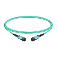
1m (3ft) 12 Fibers Female to Female MPO Trunk Cable Polarity B LSZH OM3 50/125 Multimode Fiber
$20.00
-
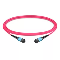
1m (3ft) 12 Fibers Female to Female MPO Trunk Cable Polarity B LSZH Multimode OM4 50/125
$21.00
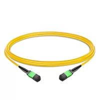
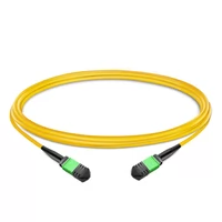
-
1m (3ft) 12 Fibers Female to Female MPO Trunk Cable Polarity B LSZH OS2 9/125 Single Mode
$26.00
-
1m (3ft) MPO UPC Female to 4 LC UPC Duplex OM3 50/125 Multimode Fiber Breakout Cable, 8 Fibers, Type B, LSZH, Aqua
$20.00
-
1m (3ft) MPO UPC Female to 4 LC UPC Duplex OM4 50/125 Multimode Fiber Breakout Cable, 8 Fibers Type B, LSZH, Aqua/Violet
$23.00