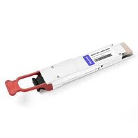
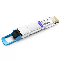
Table of Contents
ToggleWhat is an “Optical Transceiver“
Is it an optical module that is packaged with a chip?
Today we will talk about what is considered an optical module as understood by the industry.
Optical module is a component of fiber optic communication link, and fiber is the main character of fiber optic communication.
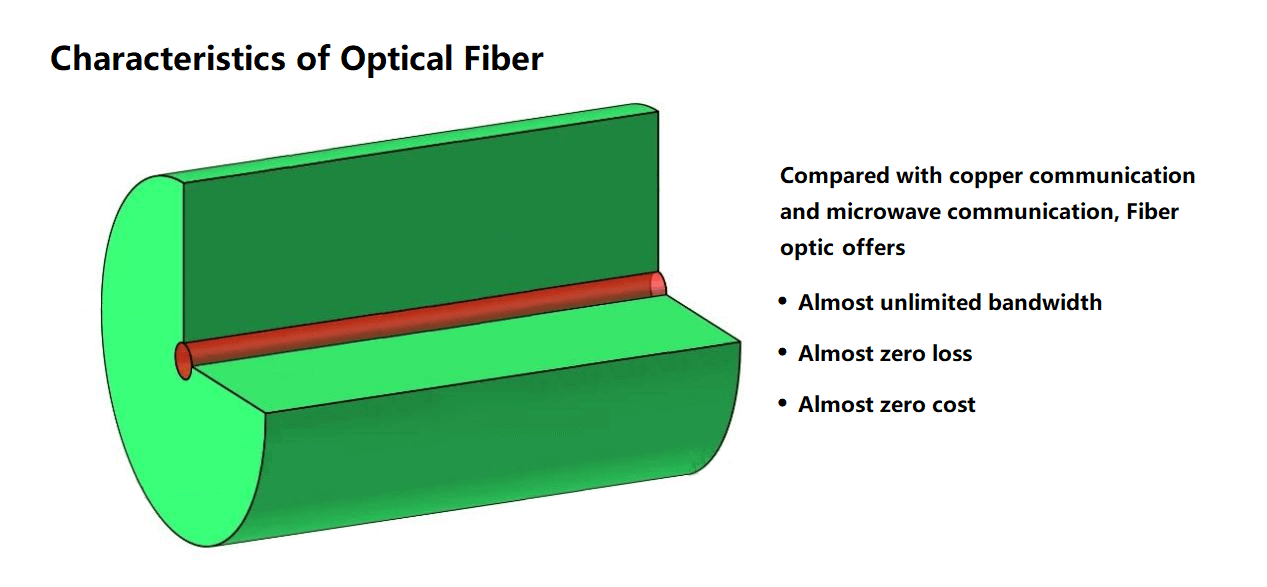
Optical fiber has a huge bandwidth, the carrier frequency of light is about 200 THz, which is hundreds of thousands of times that of microwave carriers. Call it an almost infinite bandwidth.
Optical fiber has ultra-low loss. The electrical signal of the optical transceiver, 112G XSR distance of about 150mm long, loss of 22dB. 22dB loss, that is 99.3% of the energy is consumed. 112G electrical signal 150mm length, consumed 22dB. 112G optical signal transmission on the fiber, according to the loss of 0.2dB/km for calculation, 110km, consumed 22dB. the same signal The same signal is transmitted by electricity for 150mm and light for 110km, which is quite a big difference. So call the optical fiber almost zero loss.
Optical fiber is made from glass drawn into fine filament fibers and is sold at a very low price. Compared to copper cable, called almost zero cost.
The signal transmitted by optical fiber is “light”. Light is an electromagnetic wave, which has kinetic energy, in other words, light cannot be stationary.

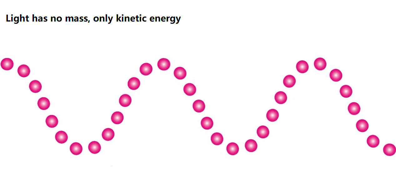
The transmission of light in optical fiber has an ultra-low cost. Due to its inability to be stationary, it is difficult to achieve low cost for signal switching, storage, and computation.
It is not that light cannot achieve switching or computing. Because there are optical switches, there are also simple calculations with light, and of course light can achieve indirect storage. For example, CD-ROM, but light can not realize low-cost switching, computing, and storage.
Between the transmission and exchange of massive amounts of information, there is an equally massive amount of signal conversion required. There is a need to convert optical signals to electrical signals, and also electrical signals to optical signals.
How can we achieve low cost for the interconversion of photoelectric signals of huge amount of information? It can be done by achieving standardization.
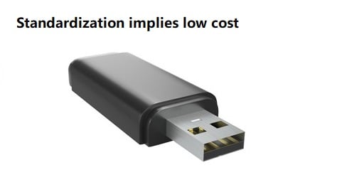
USB is a standardized interface, such as cell phone Type C data cable, from the market can be very cheap to buy, the reason is standardization.
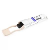
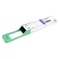
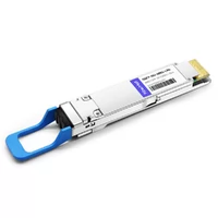
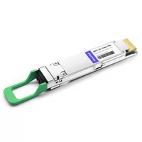
The optical transceiver is the standardized conversion interface between the electrical signal and the optical signal. Because we need to convert from optical signals to electrical signals, standing in the light, which is receiving. It also needs to convert electrical signals to optical signals, standing in the light, which is transmitting.
Therefore, the optical module is usually do both receiving and transmitting, also called as optical transceiver module.
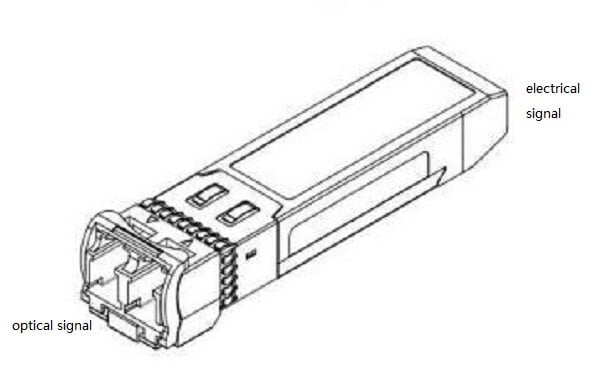
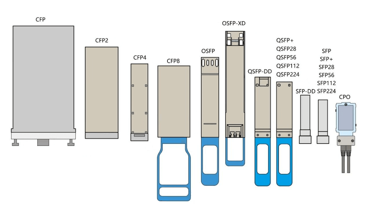
Since the standardization is defined in order to reduce costs, the optical interface in the optoelectronic interface is required to do the adaptation of the standard size.
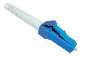
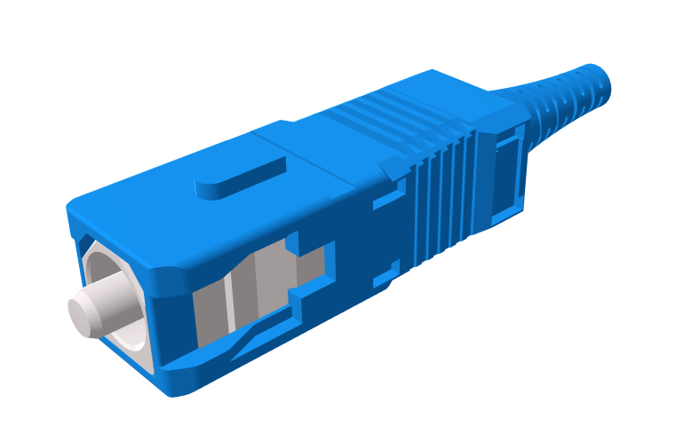
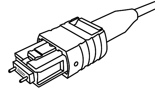
Electrical signals are also required to standardize the size of the external dimensions.
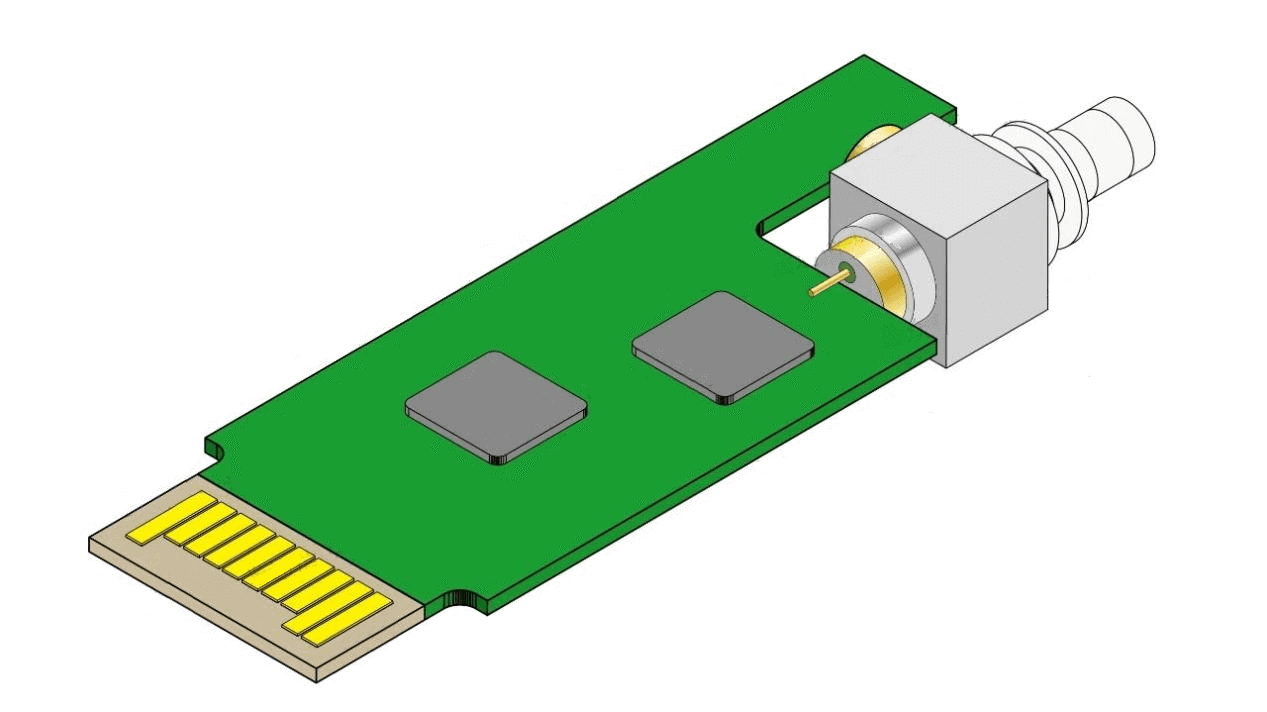
The appearance of the entire module, all aspects need to be defined clearly, to maximize the reduction of industrial costs.
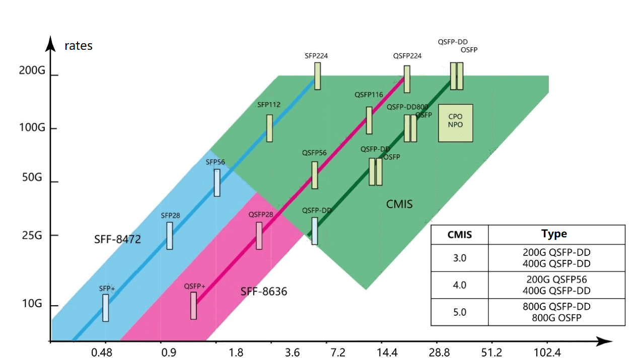
In optical transceivers, a lot of information needs to be calibrated and detected. For the management of the channel register is also standardized definition. Which register of which bit represents what meaning, but also written clearly.
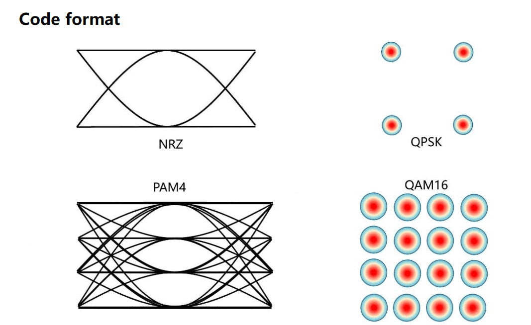
Optical modules are designed to transmit signals, and interoperability is defined for signal-related coding formats, coding amplitude phase signal quality, and so on.
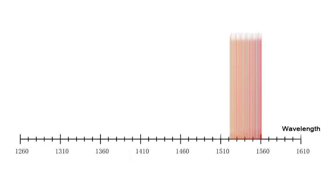
The same content related to optical signals needs to be matched with the performance of optical fibers, as well as the needs of application scenarios, to find that relatively low-cost idea in the industry, to classify the information related to wavelengths, and to do unification requirements for similar products.
The core of optical transceiver is “interoperability”, low cost, and standardization, but there are always some products that want to break away from this idea and make customization and non-standardization.
There are two reasons.
The first is that the industry scale of the segment is not large enough. For example, the backbone network of the coherent transceiver, in fact, a large proportion is difficult to multi-manufacturer fully interoperable. The total market volume of some backbone optical modules is small compared to the market volume of hundreds of millions / tens of millions of access networks. There are not many manufacturers capable of making backbone network backbone modules. If full interoperability is to be achieved, it will take a long time to be discussed in the industry, and the time cost, industry window, and industry scale, are not enough to support it. That is, interoperability and low cost cannot be equated when the market volume is not large enough.
The second reason is the competitive relationship between the industry. If the products made by factory A and factory B can be fully interoperable, customers are happy and suppliers are unhappy. And in some manufacturers who have the right to speak, they will make customized products. This situation is not the lowest cost option for the industry, but for some manufacturers it is the option to maximize benefits.
Standardization of optical modules refers mainly to software hardware and signals. For the internal implementation method, standardization is not necessarily required.
For example, the choice of silicon photonics integration solution, or InP integrated solution, or the traditional discrete solution, different manufacturers can have different forms and options.
What is an Ethernet Optical Module
An optical transceiver is simply a conversion interface for optoelectronic signals.
An Ethernet optical module is an optical module used for Ethernet. What is Ethernet? A network communication technology that can support a local area network (LAN) through message management (MIB) and public physical medium address control (MAC).
LAN, local area network.
A network that interconnects within a building or a network that interconnects in a city can be called a LAN. For example, Wuhan is a mega city, and the central city spans tens of kilometers.
Therefore, we often hear about Ethernet transmission distance of 40km, 10km, 100m, etc.
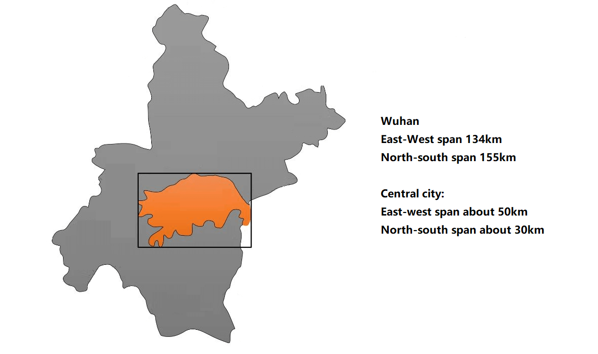
Ethernet is a technology that can support LAN communication, in other words, there are other technologies that can support LAN communication. For example, Infiniband.
Among LAN technologies, Ethernet is the most widely used and accounts for the largest share, which is characterized by information management (MIB) and public physical medium address control (MAC)
We can hardly get away from the word address for MAC. Ethernet is approximately equal to a courier company, for how our information (courier) is managed by address control, logistics in order to achieve accurate delivery between the shipper and the harvester.
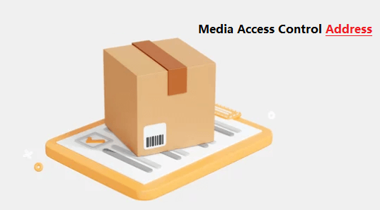
The user packages the courier (frames of Ethernet) and hands it over to the logistics company, transfers it (switch and optical transceiver), and finally delivers it to the receiver.


Ethernet is one of the city logistics couriers. If you want to go out of the city across the province, you usually need to convert and package the information again and use the WDM (e.g. train) system for long distance transmission. This time the logistics management by rail freight to operate on their own terms.

So there is a distinction between the line side and the customer side of the switch. The line side is set by the ITU-T to set standards, and the customer side is mostly the responsibility of the IEEE to set standards.
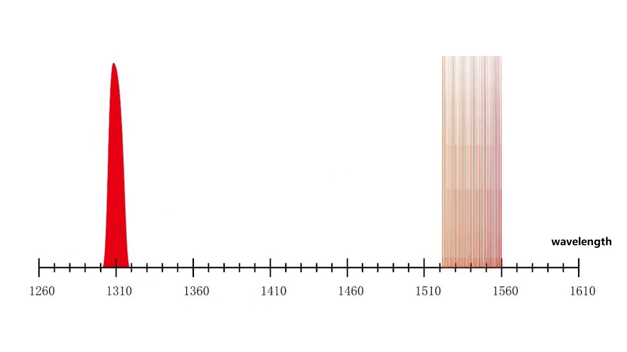
Optical modules for Ethernet, (compared to WDM coherent modules) have the following features.
Short distance: 0.1-40km
Small number of wavelengths: ranging from 1-12. For example, the number of Ethernet wavelengths in a data center is 1 or 4. 5G forward Ethernet wavelengths 1, 2, 6, 12, these wavelengths are few in number.
The transmission of more than 2 wavelengths in fiber is WDM Wavelength Division Multiplexing, BiDi, CWDM4, CWDM6, LWDM for Ethernet, and DWDM40, DWDM80… for WDM system. .96, 120, and so on.
The communication bands are mainly in the multimode 850nm and 910nm bands, as well as the single-mode O-band. These bands support low-cost lasers.
VCSELs, DFBs, and EMLs are all much cheaper than narrow linewidth tunable lasers used for wavelength division.
Optical modules for Ethernet have different rates in different scenarios. This is because LAN’s have too many network imbalances present and the choice of how large a rate optical transceiver to use depends on the application scenario.
When we mention Ethernet optical modules, it does not include WDM coherent modules and PON modules, which are understood as point-to-point transmission. But in fact, there is a part of PON module that belongs to Ethernet technology, which is the point-to-multipoint transmission of Ethernet.
Ethernet optical transceivers can be used on the customer side of metro networks, the fronthual and middlehual and backhaul of wireless access, data centers (inside) and wired access types. In the early days, the customer side and data center of MAN were divided into one category, and later on, the customer side and data center were slowly divided into two categories again.
This division can be understood as the early data centers were smaller and could share common modules on the customer side of the metro network.
Later, data centers became larger and larger, and custom dedicated optical modules were more in line with the industry’s demand for the best price/performance ratio, higher efficiency and lower (unit) cost.
WDM long-range transmission modules, which were general-purpose in earlier years, were used for interconnection between data centers, which also used WDM system to transmit their own data in earlier years, and then there was a private network between DCs as the traffic between data centers became larger and larger.
It is also understandable why there are many common choices in the scenarios of MAN customer side, backhaul in the front pass of wireless access, inside data center and wired access, while there are many common choices in the traditional WDM and private network behind DCI (such as 400GZR).

What is a Wireless Base Station Optical Module
We have two ways to make phone calls, landline and cell phone.

In addition to making phone calls, we also have the need to access the Internet. Similarly, one is through fixed network (referred to as fixed network) and the other is through cell phone to access the Internet, also known as mobile network, mobile communication.
The previous coaxial cable and copper wire is wired communication. Later, because the amount of information is too large, there is a fiber optic copper wire. Optical fiber is the fiber that transmits the signal, transmits a large amount of information. This fiber is also the line, also belongs to the category of wired communication.
From the very beginning, mobile communication has had a return line. In earlier years, it was copper wire, and later it was optical fiber. If you use optical fiber, of course, you need optical modules.
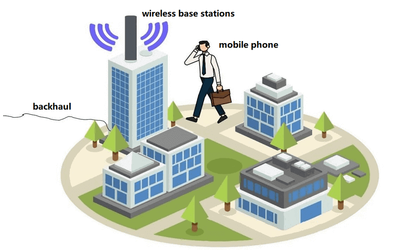
Mobile base stations to cover a certain range to contact with cell phones. So it needs to transmit electromagnetic waves down from high places.
Network equipment is needed to transmit and receive signals.
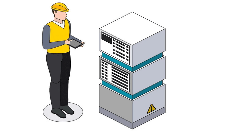
In the era of 1G and 2G, the equipment of these wireless base stations was placed high up, along with the antennas.
5G base stations use 25G optical modules. In other words, the fifth-generation mobile base stations use the advanced optical transceiver that can process 25 billion bits of information per second.
1G base station is analog communication, the quality is not good, the number of access is also limited. 2G base station, the use of digital communication, but also opened up a variety of digital coding technology industry.
Back to the topic, there are some problems with putting the wireless base station equipment up high.
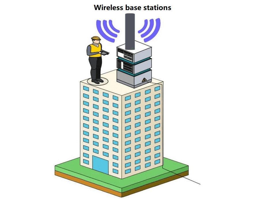
The problem is that both the preliminary installation and later maintenance require labor to climb high buildings with the equipment.

And as more and more people use cell phones, the more base stations are built, the labor costs are very high. Wait until the third generation of mobile base stations, some manufacturers are considering how to reduce this cost.
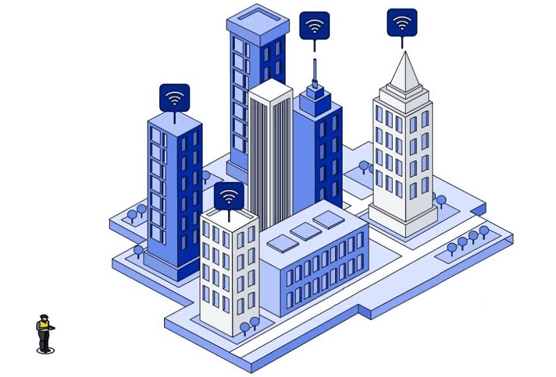
Split the base station equipment, but the antenna must be placed on high. The rest of the parts that can’t be moved follow the antenna on high. Those that can be moved will be put downstairs.
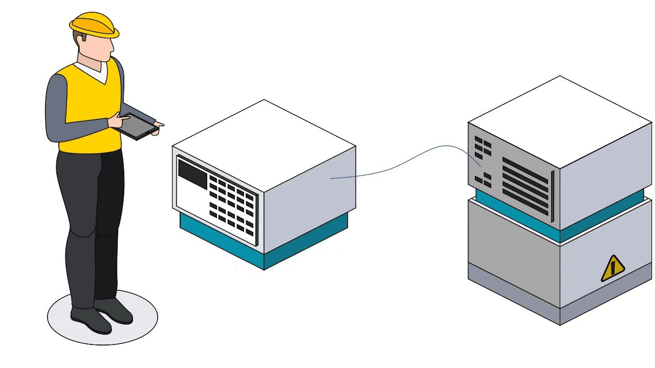
This gave birth to BBU and RRU.
RRU is mainly the part of RF wireless, BBU is mainly the part of digital baseband, BBU is the part that can be separated from the antenna.
The communication line between RRU and BBU is called ” fronthaul “.
In the early days of forward transmission, optical modules were not necessarily needed, and copper wires at low frequencies could be used for long distance transmission. If there are many users, the amount of information is very large, copper will have a high frequency skin effect.
If the distance is not far, the deployment cost is cheaper with multimode fiber. So the fronthaul optical transceiver earlier is a lot of multimode modules.
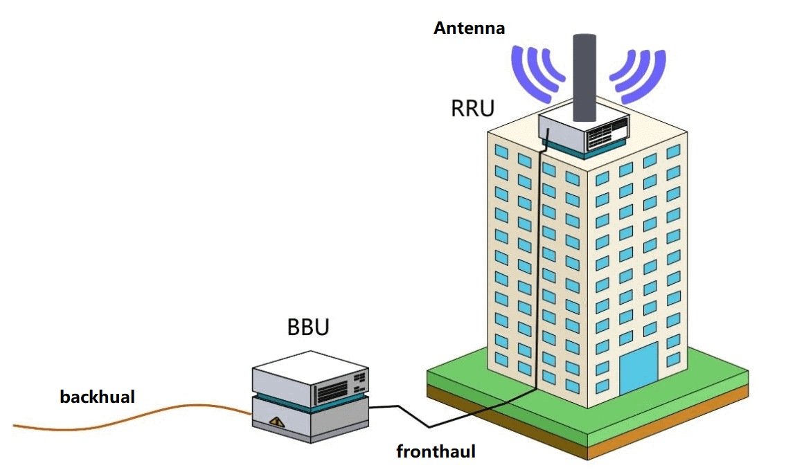
Fiber optics is characterized by high capacity and long distances. By putting BBUs together, analysis, location and maintenance become easy.
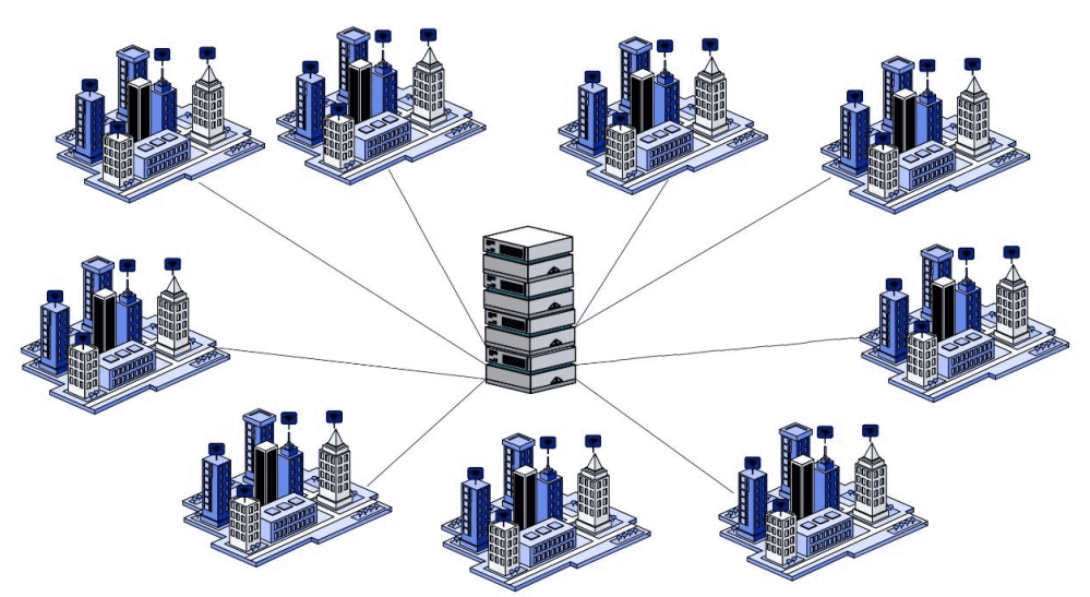
The technical support for fiber optic communication is remote. It is the change of fiber from multi-mode to single-mode for AAUs and BBUs.
After remote, the BBU is in the CO, the central office, called the bureau. A BBU, management of a bunch of RRU, RRU later can also be light, is RRH, the H is Head, just a head left on the remote end.
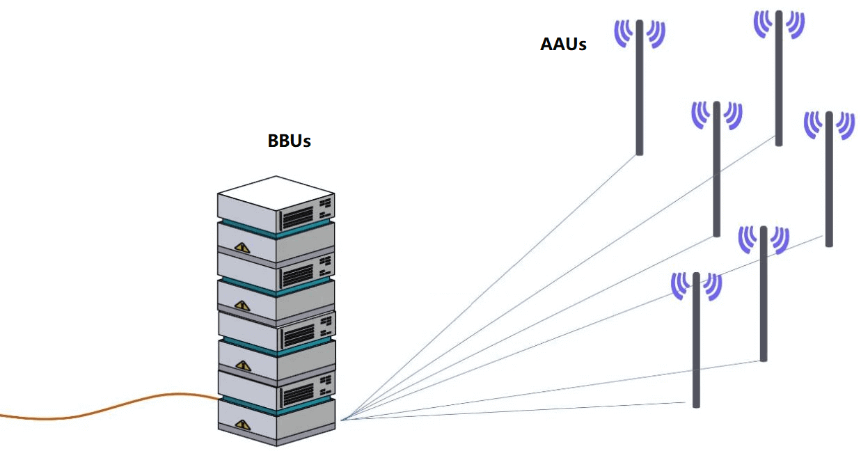
3G and 4G, both have only fronthual and backhaul.
The fronthual is the connection between BBU and RRU/RRH. The backhaul is the connection between the main network and the BBU, and this has fewer fibers and fewer optical modules. But each optical transceiver has more capacity, each fiber has more capacity, and information is not lost.
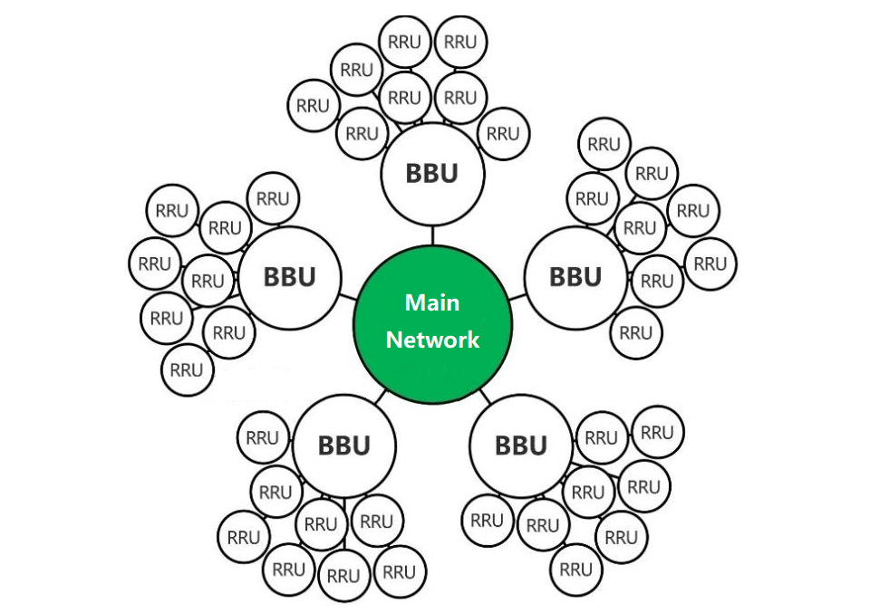
By the time 5G comes around, it’s time to think about how to be more efficient, lower cost, and higher capacity.
RRU/RRH and antenna are integrated, called AAU.
BBUs are decomposed again and divided into CU and DU. The main network is connected to many CUs, one CU is connected to many DUs, one DU is connected to many AAUs.
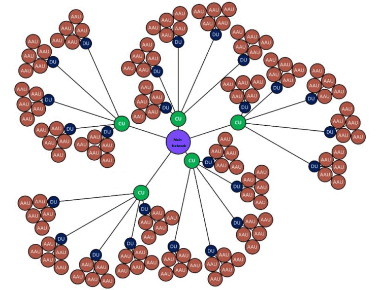
If the BBU continues to split into CU and DU, this section is just between the backhual and fronthual, named the middlehual.
If doing so does not reduce costs, the BBU is retained.
So in the early days of 5G deployment, there was no separate definition of a middlehual optical transceiver. The standard retains this function, if needed, continue to split. This is similar to the soft folding layer of some luggage “expandable”.

Optical modules used in base stations are essentially a wired communication concept, and the optical modules are connected by “optical fiber”.
When we talk about wireless base station optical modules, we are referring to wired (fiber optic) communication optical modules used in wireless RF communication scenarios.
There is another category of truly wireless optical communication, where light is transmitted through the air for communication. This type of optical transceiver is called FSO, free space optics, which is different from non-free space fiber optic waveguide wired communication.
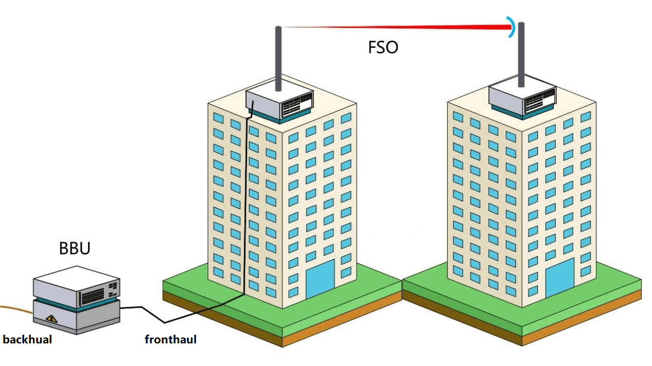
FSO true wireless optics communication used in a higher capacity than microwave communication bandwidth. For example, communication between satellites, it is difficult to dump a communication line in space, and the need for high-capacity communication.
Space optics communication, with the benefits of wireless, also has the benefits of greater bandwidth than microwave communications.
Ordinary people call, wireless this little distance or low-frequency electromagnetic wave carrier, not space (high-frequency) optical carrier communication, FSO communication costs are very high.
Related Products:
-
 QSFP56-200G-SR4M 200G QSFP56 SR4 PAM4 850nm 100m MTP/MPO APC OM3 FEC Optical Transceiver Module
$139.00
-
 QSFP56-200G-FR4S 200G QSFP56 FR4 PAM4 CWDM4 2km LC SMF FEC Optical Transceiver Module
$650.00
-
 QSFP-DD-400G-LR4 400G QSFP-DD LR4 PAM4 CWDM4 10km LC SMF FEC Optical Transceiver Module
$600.00
-
 QSFP-DD-400G-FR4 400G QSFP-DD FR4 PAM4 CWDM4 2km LC SMF FEC Optical Transceiver Module
$500.00
-
 QSFP-DD-400G-ER4 400G QSFP-DD ER4 PAM4 LWDM4 40km LC SMF without FEC Optical Transceiver Module
$3500.00
-
 QSFP-DD-400G-XDR4 400G QSFP-DD XDR4 PAM4 1310nm 2km MTP/MPO-12 SMF FEC Optical Transceiver Module
$580.00
-
 QSFP28-100G-IR4 100G QSFP28 IR4 1310nm (CWDM4) 2km LC SMF DDM Transceiver Module
$110.00
-
 QSFP28-100G-LR4-20 100G QSFP28 LR4 1310nm LWDM4 20km LC SMF DDM Transceiver Module
$300.00
-
 QSFP28-100G-SRBD Dual Rate 40G/100G QSFP28 BIDI 850nm & 900nm 100m LC MMF DDM Optical Transceiver
$449.00
-
 QSFP28-100G-ER4L 100G QSFP28 ER4 Lite 1310nm (LAN WDM) 40km with FEC,30km without FEC LC SMF DDM Transceiver Module
$800.00
-
 QSFP28-100G-ZR4 100G QSFP28 ZR4 1296-1309nm LWDM 80km LC SMF DDM Transceiver Module
$1500.00
-
 QSFP28-100G-LR4 100G QSFP28 LR4 1310nm (LAN WDM) 10km LC SMF DDM Transceiver Module
$285.00
-
 SFP28-25G-SR 25G SFP28 SR 850nm 100m LC MMF DDM Transceiver Module
$25.00
-
 SFP28-25G-LR 25G SFP28 LR 1310nm 10km LC SMF DDM Transceiver Module
$45.00
-
 SFP28-25G-ESR 25G SFP28 ESR 850nm OM3 200m/OM4 300m LC MMF DDM Transceiver Module
$35.00
-
 SFP28-25G-ER 25G SFP28 ER 1310nm 40km LC SMF DDM Transceiver Module
$125.00
-
 SFP28-25G-ER30 25G SFP28 ER Lite 1310nm 30km LC SMF DDM Transceiver Module
$165.00
-
 SFP28-25G32-BX10I 25G BX BIDI SFP28 TX1330nm/RX1270nm 10km LC SMF DDM Industrial Transceiver Module
$50.00
-
 SFP28-25G32-BX40 25GBASE SFP28 BIDI ER TX1310nm/RX1270nm 40km LC SMF DDM Optical Transceiver Module
$180.00
-
 SFP28-25G32-BX40I 25GBASE SFP28 BIDI ER TX1310nm/RX1270nm 40km LC SMF DDM Industral Optical Transceiver Module
$200.00

