More than 300 years ago, on a sunny afternoon, Newton laid out such a game.
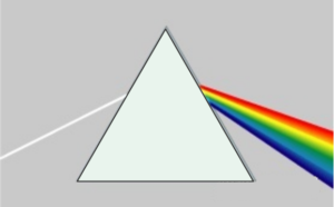
Figure1: Refraction of light by a prism
He let the sun shine on the prism. After penetrating the prism, the light spread out into a ribbon composed of red, orange, yellow, green, blue, blue, and purple light, and projected onto a curtain in the room. In this way, the seemingly transparent sunlight changes into an incredible color band through the prism.
After that, Newton opened a vertical slit in the middle of the curtain and set a second prism and a second curtain behind the curtain. He turned the first prism and projected the seven ribbons into the cracks of the first curtain in turn, and then projected them onto the second curtain through the second prism. A miracle happened — the light was separated into a variety of single colors and presented on the second curtain. The schematic is shown below:
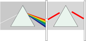 Figure2: the second refraction of light
Newton used the prism to uncover a mystery: light can be dispersed! That is what we now call the chromatic dispersion of light.
How does chromatic dispersion arise?
In the triangular prism experiment, sunlight (compound light) enters the glass from the air, and then enters the air from another glass, which is refracted twice. It’s known that everything tends to seek profits. When refraction occurs, the light will choose the shortest path and move forward while minimizing energy loss. From Newton’s prism experiment, we know that composite light is composed of many single lights of different colors. These lights have different wavelengths, and the energy of different wavelengths of light is uneven. Lights with different wavelengths also have differences in how to choose the route after refraction, so they “parted ways” after getting out of the prism.
So, why is the light scattered? It turns out that it is the wavelengths of light that cause chromatic dispersion. Different wavelengths of light have different refractive indices and different propagation speeds (paths) in different mediums, which will inevitably cause the light to spread dispersively, and dispersion is formed.
The dispersion of light shows that the speed of light propagation in a medium has a great relationship with the refractive index. The greater the refractive index, the smaller the speed of light. Here is the formula:
V=C/N, C is the propagation speed of light in a vacuum (constant at 300,000 km/s); N is the refractive index of medium to light.
The effect of chromatic dispersion
Although dispersion can lead us to a colorful world, dispersion is not so beautiful in the field of communication. Chromatic dispersion is one of the important factors leading to loss during optical signal transmission in optical fiber. That is because the refractive index of the light causes dispersion, and dispersion causes the optical pulse to generate inter-symbol interference, which results in broadening at the output end.
What is broadening?
Broadening is the increase in the spectral width of light of different wavelengths in the medium due to the different refractive indices that lead to different propagation speeds. In other words, when a beam of light is transmitted in a medium, some light waves have a large refractive index, which seriously deviates from the runway.
Some light waves have a small refractive index, and although they are crooked, they can move in a given direction. The disharmony of the light waves causes the width of this beam of light to be larger than it was before entering the medium, resulting in broadening.
In the case of chromatic dispersion, the longer the distance of optical signal transmission, the more serious the spread. The results are signal distortion and bit error rate performance deterioration, which severely affect the quality of information transmission. How do we avoid the impact of dispersion on communication?
How do we avoid the effect of chromatic dispersion?
After a long period of exploration and research, people have found a compensation method to balance the loss of dispersion. The dispersion compensation fiber (DCF) technology is a highly recognized dispersion compensation method among various methods.
In a common single-mode fiber system, the fiber has a high positive dispersion at an operating wavelength of 1550 nm. The characteristic of positive dispersion: as the wavelength increases, the refractive index gradually decreases. It is necessary to add negative dispersion in these fibers for compensation to ensure that the total dispersion of the entire fiber line is approximately zero. The dispersion compensating fiber (DCF) is a new type of single-mode fiber mainly designed for the wavelength of 1550nm. DCF has a high negative dispersion at 1550nm (Negative dispersion has the opposite qualities of positive dispersion) and can be used for dispersion compensation in single-mode fiber systems. As shown in the figure below, the sum of the compensated positive and negative dispersion approaches zero at 1550nm.
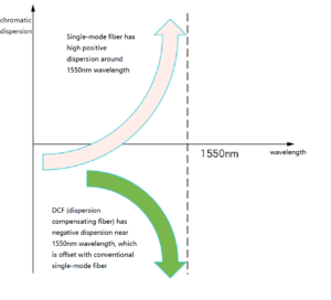
Figure3: Schematic diagram of dispersion compensation of DCF
The following is the formula for DCF applied to single-mode fiber:
D( λs)L +Dc(λs)L c=0
D( λ s) is the dispersion coefficient of the single-mode fiber at the working wavelength λ s;
Dc( λ s) is the dispersion coefficient of DCF at the operating wavelength λ s.
L and LC are the lengths of conventional single-mode fiber and DCF, respectively.
In practical applications, DCF and single-mode fiber are connected in series in the transmission line to compensate for the positive dispersion of single-mode fiber at 1550nm. In doing so, the relay distance is extended and loss reduced, and high-speed, large-capacity, and long-distance communication can be achieved. As shown below:

Figure4: DCF and single-mode fiber are connected in series
DCF has the following advantages:
- The compensation effect is remarkable, and the system works stably;
- Easy to operate, the compensation fiber can be directly connected to the transmission system to realize compensation;
- The amount of dispersion compensation is controllable on demand and can be adjusted according to the actual compensation amount required by the transmission system
As the optical signal travels longer on the transmission line, other losses will occur, such as line attenuation. It is necessary to consider using EDFA (Erbium-Doped Fiber Amplifier) to avoid line attenuation.
Table of Contents
ToggleRelated Products:
-
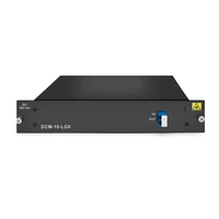
 DCM 10km DCF-based Passive Dispersion Compensation Module, 2.6dB Low Loss, LC/UPC Connector
$439.00
-
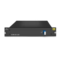
 DCM 20km DCF-based Passive Dispersion Compensation Module, 3.5dB Low Loss, LC/UPC Connector
$499.00
-
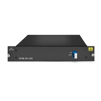
 DCM 30km DCF-based Passive Dispersion Compensation Module, 3.8dB Low Loss, LC/UPC Connector
$539.00
-
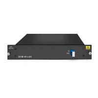
 DCM 40km DCF-based Passive Dispersion Compensation Module, 5.2dB Low Loss, LC/UPC Connector
$579.00
-
 DCM 60km DCF-based Passive Dispersion Compensation Module, 6.8dB Low Loss, LC/UPC Connector
$869.00
-
 DCM 80km DCF-based Passive Dispersion Compensation Module, 8.0dB Low Loss, LC/UPC Connector
$929.00
-
 DCM 100km DCF-based Passive Dispersion Compensation Module, 9.5dB Low Loss, LC/UPC Connector
$1159.00
-
 DCM 120km DCF-based Passive Dispersion Compensation Module, 11.5dB Low Loss, LC/UPC Connector
$1299.00

