
Introduced the world’s first 800G active cable (AEC) product with a barebone digital signal processor (DSP) at DesignCon 2025. Scheduled for a Q4 2024 release, this breakthrough innovation removes the conventional packaging layer of the DSP chip. Instead, the DSP’s bare die is directly embedded into the cable assembly using Chip on Board (COB) and mSAP processes.
This novel design eliminates traditional packaging and intermediary layers. Through meticulously optimized pin mapping, state-of-the-art packaging techniques, a well-considered layout configuration, and refined termination of conductors, the design significantly enhances signal integrity. Moreover, the integration of the bare die delivers a marked improvement in thermal performance. Unlike conventional packaged DSPs, which often suffer from poor heat dissipation due to structural limitations and are prone to overheating, thereby jeopardizing component lifespan and performance, the bare-die approach permits the direct application of thermal interface material (TIM) and heat sinks on the chip surface. This direct integration substantially improves thermal efficiency, effectively addresses heat dissipation challenges, and ensures stable performance even during high-speed operation.
Notably, the technology is forward-looking and compatible with 224G solutions, making it suitable for various wiring applications in both optical communications and active copper cables. This universality underscores its strong versatility.
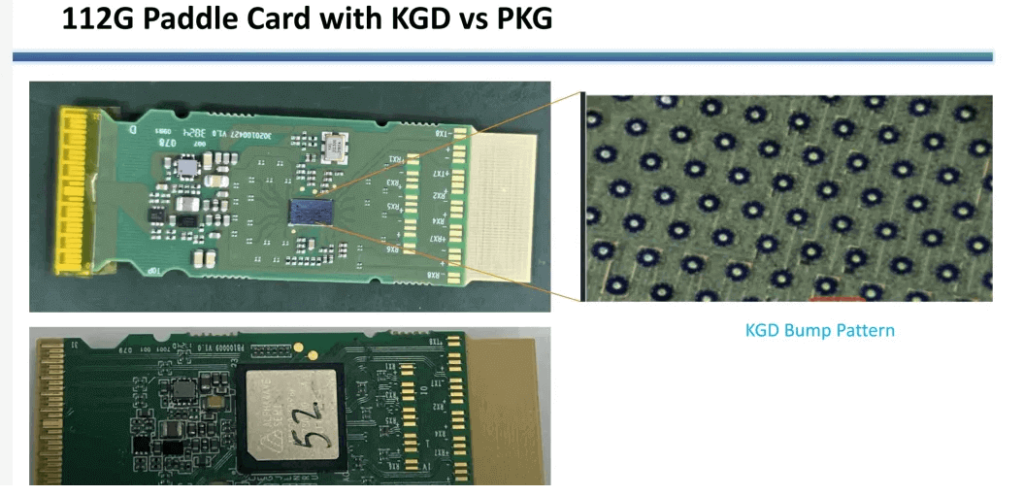
In this design, COB and mSAP technologies play critical roles. COB technology involves directly mounting and bonding the bare semiconductor chip onto a printed circuit board (PCB), thereby shortening interconnect paths, reducing physical footprint, enhancing signal integrity, and lowering production costs. Conversely, mSAP technology focuses on achieving extremely fine trace widths and spacings, enabling the fabrication of high-precision circuit patterns that improve the electrical performance of the PCB. Together, these technologies establish a robust foundation for the miniaturization and enhanced performance of advanced electronic devices.
Performance Analysis of Traditional Packaged DSPs
A comparative performance analysis was conducted using a traditional packaged DSP to thoroughly assess the advantages of the bare-die (KGD) design. The study employed Alphawave Semi’s Cu-Wave AW100 packaged digital signal processor, integrated into an 800G OSFP copper cable assembly.
(1) Signal Integrity Simulation
Host-Side Simulation
The simulation primarily considered the signal path from the DSP to the connector’s golden fingers on the host card. Megtron 7 was used as the PCB material, characterized by a dielectric constant (Dk) of 3.3 and a dissipation factor (Df) of 0.0015 at 1 GHz.
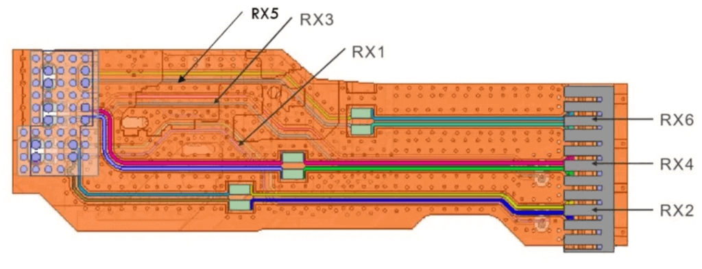
At a Nyquist frequency of 26.56 GHz—corresponding to a 106.25 Gbps PAM4 signal—the receiver channels RX1 through RX6 exhibited insertion losses ranging from 1.4 dB to 1.6 dB, demonstrating minimal attenuation and high transmission efficiency. Furthermore, return loss (RL) values remained below −10 dB for frequencies up to 30 GHz, indicating minimal signal reflection and thereby contributing to superior signal integrity and system reliability.

In terms of crosstalk, key adjacent channel pairs (such as RX3–RX5 and RX3–RX1) revealed near-end crosstalk (NEXT) levels around −48 dB and far-end crosstalk (FEXT) around −42 dB at 26.56 GHz, which confirms effective suppression of interference.
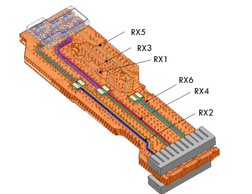
Line-Side Simulation
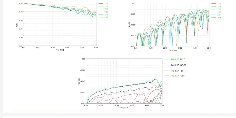
The simulation on the line side encompassed the complete signal path from the DSP to the cable termination, including both transmitter (TX) and receiver (RX) channels. Due to variations in trace lengths and routing methods, receiver channels RX6, RX7, and RX8 manifested differing insertion loss values. Specifically, RX6, benefiting from a shorter trace, exhibited an insertion loss of approximately 0.6 dB at 26.56 GHz, whereas RX7 and RX8 recorded insertion losses between 1.2 dB and 1.3 dB. Similarly, transmitter channels TX1, TX2, and TX3 demonstrated insertion losses in the range of 1.2 dB to 1.5 dB, which collectively indicate acceptable transmission performance.
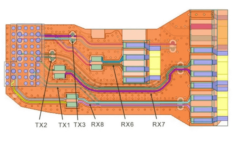
The line-end return loss was maintained below −11 dB at the Nyquist frequency, evidencing proper impedance matching and effective control of signal reflections. Furthermore, crosstalk analysis of adjacent channel pairs—such as RX8–RX7 and TX2–RX7—showed that at 26.56 GHz, the RX8–RX7 pair achieved NEXT and FEXT values of −48 dB each, while the TX2–RX7 pair exhibited NEXT as low as −58 dB and FEXT as low as −60 dB. These results underscore the design’s efficacy in isolating differential pairs and markedly reducing interference.
(2) Thermal Simulation
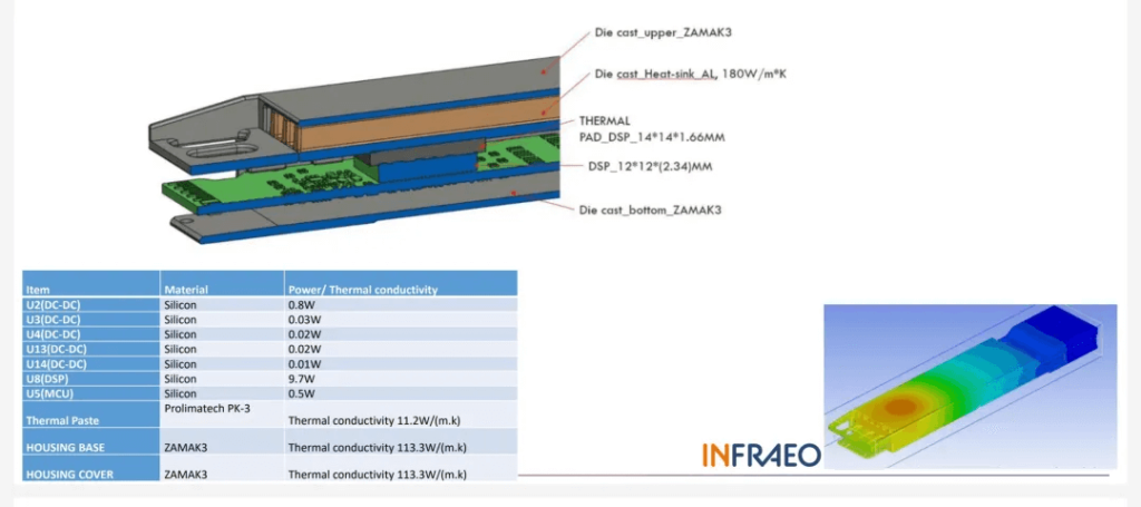
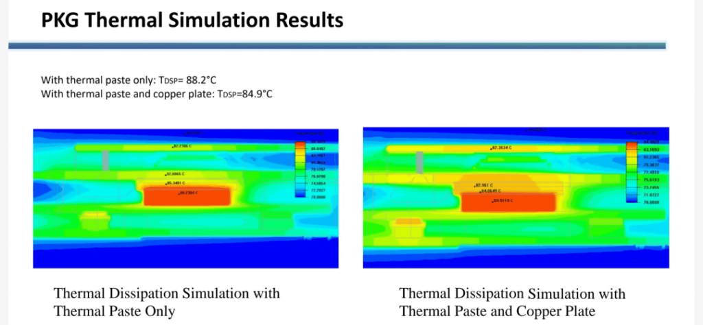
Thermal simulations were conducted under stringent conditions, with an ambient temperature of 70°C and a power consumption below 10 W. The simulation model incorporated the Cu-Wave AW100 packaged DSP along with other critical components, employing advanced thermal management materials such as Prolimatech PK-3 thermal grease. In the baseline configuration—using solely thermal grease—the DSP’s surface temperature reached 88.2°C, thereby exceeding the operational limit of 85°C. This outcome indicates that the baseline design is inadequate for reliable operation under extreme conditions. However, with the addition of a copper plate, the DSP’s surface temperature was effectively reduced to 84.9°C, successfully maintaining it within a safe operating range. This result validates the effectiveness of combining high thermal conductivity materials with an optimized thermal interface to address heat dissipation challenges.
Performance Advantages of the KGD DSP
The following analysis focuses on the performance of the KGD DSP. The Cu-Wave AW100 DSP in the KGD configuration retains the same core functionalities as its packaged counterpart, supporting the IEEE 802.3ck Chip-to-Module (C2M) and Chip-to-Chip (C2C) standards along with advanced equalization techniques that guarantee reliable signal transmission even in complex electrical channels. Unlike the packaged version, the KGD DSP is directly mounted on the PCB using flip-chip technology. This method minimizes parasitic effects caused by wire bonding, thereby improving signal integrity and reducing latency.
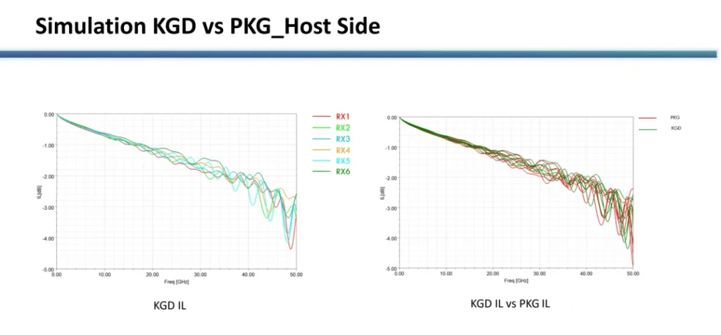
Host-Side Simulation
In the host-side simulation, the KGD DSP channels (R1–R6) are equivalent to those of the packaged version, permitting a direct comparison. Analysis of the insertion loss (IL) results at a Nyquist frequency of 26.56 GHz reveals that, for most channels, the KGD DSP demonstrates an improvement of approximately 0.5 dB over the packaged version. This benefit is primarily due to the smaller via diameters, which reduce capacitance and increase impedance by roughly 1 ohm, ultimately enhancing data transmission performance.
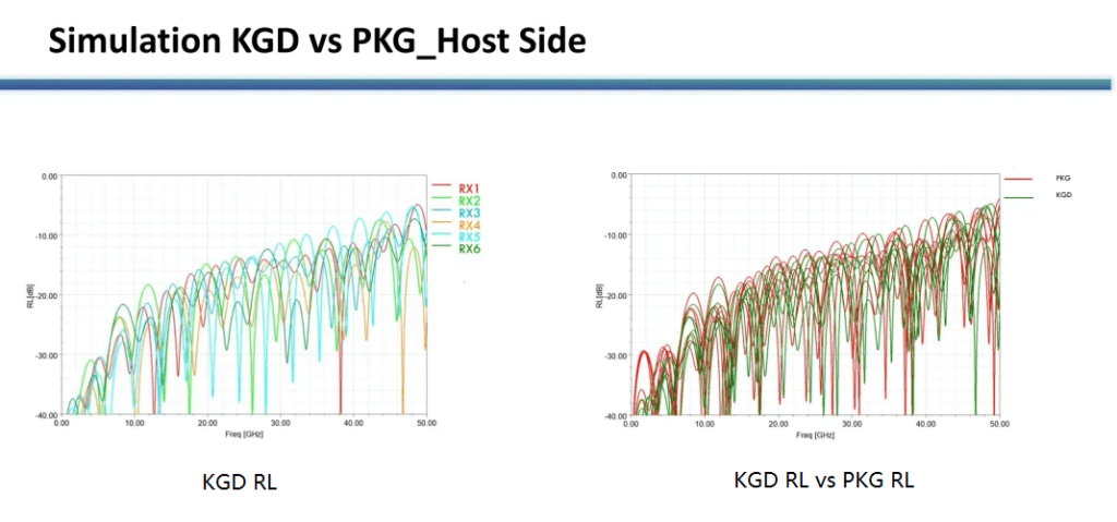
In terms of return loss (RL), the RX1–RX6 channels of the KGD DSP maintain RL values below –9 dB for frequencies below 30 GHz—a 1 dB improvement compared to the packaged version—thanks to an optimized trace impedance that more closely approximates 87.5 Ω.
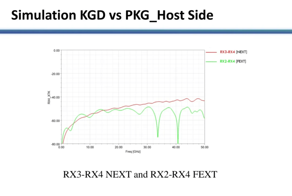
Additionally, crosstalk evaluation—examining the worst-case channels such as RX3–RX4 NEXT and RX2–RX4 FEXT—indicates that the RX3–RX4 NEXT remains below –40 dB for frequencies up to 50 GHz, whereas the worst-case crosstalk channel of the packaged version (RX1–RX3) exceeds –40 dB at 40 GHz. This enhancement is attributable to an improved trace layout that increases the spacing between differential pairs, thereby effectively reducing interference.
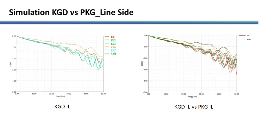
Line-Side Simulation
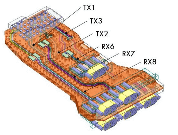
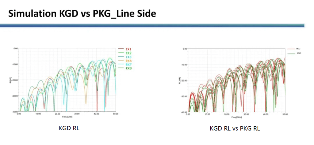
The line-side simulation model extends from the DSP to the cable termination, assessing the SI performance of the transmitter channels (TX1, TX2, TX3) and receiver channels (RX6, RX7, RX8). The insertion loss at 26.56 GHz for the KGD mezzanine card’s line-end shows an improvement of approximately 0.2 dB relative to the packaged version. Concerning return loss, the RX1–RX6 channels of the KGD DSP sustain RL values below –10 dB for frequencies under 30 GHz, which is slightly better than that of the packaged version.
For crosstalk, analysis of the worst-case channels (such as RX8–RX7 NEXT and RX8–RX7 FEXT) demonstrates that RX8–RX7 FEXT remains below –40 dB for frequencies under 40 GHz. In contrast, the worst-case crosstalk channel in the packaged version (RX5–RX3) exceeds –40 dB at 40 GHz. This superior performance is mainly due to the increased spacing of 40 mil between differential pairs in the KGD design, which effectively optimizes the trace layout and reduces crosstalk.

Thermal Simulation
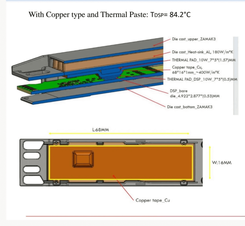
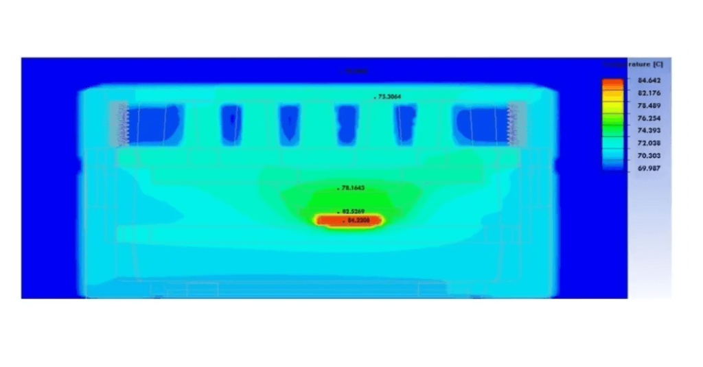
Managing heat dissipation for the DSP bare die is challenging because the same power must be dissipated across a smaller surface area. In the thermal simulation, a maximum power of less than 10 W was applied to the KGD bare die. A 16 × 68 mm copper strip was used to increase the heat dissipation area, while Prolimatech PK-3 thermal grease was applied between the bare die and the copper strip, as well as between the copper strip and the metal housing. Under these conditions, with an ambient temperature of 70 °C and maximum power below 10 W, the bare die’s temperature was simulated to be 84.2 °C—safely below the operating limit of 85 °C. Even though the KGD bare die occupies only one-tenth of the area of the packaged DSP, the optimized thermal interface material (TIM) solution—leveraging the copper strip’s excellent thermal conductivity and increased contact area—successfully ensures effective heat dissipation.
Summary and Outlook
The comprehensive analysis of both the traditional packaged DSP and the KGD DSP clearly demonstrates that directly integrating the KGD DSP into an active electrical cable (AEC) assembly represents a significant breakthrough in high-speed interconnect design and performance. In comparison to conventional packaged configurations, the KGD DSP exhibits remarkable advantages in signal integrity and power efficiency. By employing advanced materials such as high-thermal-conductivity copper strips and Prolimatech PK-3 thermal grease, the design effectively addresses the heat dissipation challenges imposed by the compact chip size, ensuring that the DSP operates reliably within the specified temperature range even at maximum power. These advancements pave the way for further innovations in high-speed data transmission and electronic system performance.
Related Products:
-
 OSFP-800G-AEC2M 2m (7ft) 800G OSFP to OSFP PAM4 Active Electrical Copper Cable
$935.00
OSFP-800G-AEC2M 2m (7ft) 800G OSFP to OSFP PAM4 Active Electrical Copper Cable
$935.00
-
 OSFP-800G-AEC50CM 0.5m (1.6ft) 800G OSFP to OSFP PAM4 Active Electrical Copper Cable
$875.00
OSFP-800G-AEC50CM 0.5m (1.6ft) 800G OSFP to OSFP PAM4 Active Electrical Copper Cable
$875.00
-
 OSFP-800G-AEC1M 1m (3ft) 800G OSFP to OSFP PAM4 Active Electrical Copper Cable
$895.00
OSFP-800G-AEC1M 1m (3ft) 800G OSFP to OSFP PAM4 Active Electrical Copper Cable
$895.00
-
 OSFP-800G-AEC1.5M 1.5m (5ft) 800G OSFP to OSFP PAM4 Active Electrical Copper Cable
$915.00
OSFP-800G-AEC1.5M 1.5m (5ft) 800G OSFP to OSFP PAM4 Active Electrical Copper Cable
$915.00
-
 OSFP-800G-AEC2.5M 2.5m (8ft) 800G OSFP to OSFP PAM4 Active Electrical Copper Cable
$955.00
OSFP-800G-AEC2.5M 2.5m (8ft) 800G OSFP to OSFP PAM4 Active Electrical Copper Cable
$955.00
-
 OSFP-800G-AEC3M 3m (10ft) 800G OSFP to OSFP PAM4 Active Electrical Copper Cable
$975.00
OSFP-800G-AEC3M 3m (10ft) 800G OSFP to OSFP PAM4 Active Electrical Copper Cable
$975.00
-
 OSFP-800G-AEC3.5M 3.5m (11ft) 800G OSFP to OSFP PAM4 Active Electrical Copper Cable
$995.00
OSFP-800G-AEC3.5M 3.5m (11ft) 800G OSFP to OSFP PAM4 Active Electrical Copper Cable
$995.00
-
 OSFP-800G-AEC4M 4m (13ft) 800G OSFP to OSFP PAM4 Active Electrical Copper Cable
$1015.00
OSFP-800G-AEC4M 4m (13ft) 800G OSFP to OSFP PAM4 Active Electrical Copper Cable
$1015.00
-
 OSFP-800G-AEC4.5M 4.5m (14ft) 800G OSFP to OSFP PAM4 Active Electrical Copper Cable
$1035.00
OSFP-800G-AEC4.5M 4.5m (14ft) 800G OSFP to OSFP PAM4 Active Electrical Copper Cable
$1035.00
-
 OSFP-800G-AEC5M 5m (16ft) 800G OSFP to OSFP PAM4 Active Electrical Copper Cable
$1055.00
OSFP-800G-AEC5M 5m (16ft) 800G OSFP to OSFP PAM4 Active Electrical Copper Cable
$1055.00