In the context of promoting liquid cooling technology and enhancing ecological maturity, Inspur Information and Intel have collaborated to optimize the design of liquid-cooled servers for general high-density use. Beyond the widely adopted CPU and GPU liquid cooling methods, they have also explored and researched liquid cooling solutions for high-power memory, solid-state drives, OCP network cards, PSU power supplies, PCIe, and optical modules. The goal is to achieve the industry’s highest liquid cooling coverage, meeting diverse liquid cooling deployment requirements for clients in industries such as the Internet and communications.
The development of the all-liquid-cooled blade system is based on Inspur Information’s 2U four-node high-density computing server, the i24. Each liquid-cooled node supports two Intel 5th generation Xeon Scalable processors, 16 DDR5 memory modules, one PCIe expansion card, and one OCP 3.0 network card. The entire system can accommodate up to eight SSD solid-state drives, providing both high-density computing power and storage capacity for customers. The primary heat-generating components in the server include the CPU, memory, I/O boards, local hard drives, and chassis power supply.
The liquid cooling solution efficiently removes approximately 95% of the system’s heat directly from the heat source through contact with the liquid-cooled plate. The remaining 5% of heat is carried away by the cooling water inside the air-liquid heat exchanger located behind the PSU power supply. Overall, this achieves close to 100% liquid cooling heat capture efficiency at the system level.
System Composition and Pipeline Layout
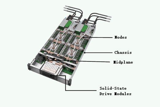
The 2U four-node all-liquid-cooled server system consists of nodes, chassis, midplane, and solid-state drive modules. The connections between node and chassis components are achieved through quick connectors for water, power, and signal blind insertion.
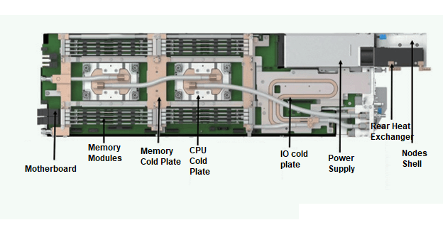
Each individual node in the all-liquid-cooled server comprises a node enclosure, motherboard, CPU chip, memory modules, memory cold plate, CPU cold plate, IO cold plate, power supply, and rear heat exchanger.
Flow Path Selection and Flow Rate Calculation
To simplify the complexity of flow path design, this all-liquid-cooled server adopts a series flow path configuration. The cooling medium flows from low-power components to high-power components, as illustrated in the diagram.
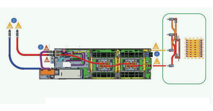
The liquid flow rate in the all-liquid-cooled server must meet the system’s heat dissipation requirements:
- To ensure the long-term reliability of secondary-side pipeline materials, the secondary-side return water temperature should not exceed 65°C.
- All components of the all-liquid-cooled server must meet heat dissipation requirements under defined boundary conditions. For flow rate design analysis, copper cold plates with PG25 are selected.
To meet the requirement of secondary-side return water temperature not exceeding 65°C, the minimum flow rate (Qmin) for a single PG25 node is calculated using the following formula: Qmin=ρ⋅C⋅ΔTPsys≈1.3LPM
CPU Cold Plate Design
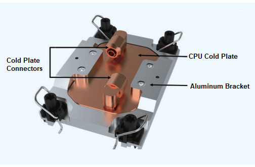
The CPU cold plate module is designed based on the requirements for Intel’s 5th generation Xeon Scalable processors. It optimizes factors such as heat dissipation, structural performance, yield, price, and compatibility with different cold plate materials. The CPU cold plate reference design primarily consists of an aluminum bracket, CPU cold plate, and cold plate connectors.
Memory Liquid Cooling Design
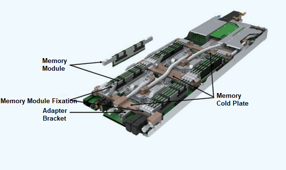
The memory liquid cooling design employs an innovative “sleeper” radiator solution, named after the way memory modules fill up like sleepers on a railroad track. It combines traditional air cooling and cold plate cooling. The heat generated by memory modules is transferred to both ends of the sleeper radiator (which contains built-in heat pipes, aluminum/copper plates, or vapor chambers). The heat is then conducted to the cold plate through selected thermal pads, and finally dissipated using the cooling medium within the cold plate.
Memory and the radiator can be assembled externally using fixtures to create the smallest maintenance unit (referred to as the “memory module” hereafter). The memory cold plate features a fixed structure to ensure good contact between the radiator and memory cold plate. Depending on requirements, the memory module fixation can use screws or tool-less mechanisms. The top of the memory cold plate handles memory heat dissipation, while the bottom can be used for other heat-generating components on the motherboard, such as VR components, maximizing the utilization of the memory cold plate.
To simplify memory cold plate design, adapter brackets can be used between memory and the motherboard to accommodate different height restrictions.
Compared to existing tubing-based memory liquid cooling solutions in the market, the sleeper radiator approach offers several advantages:
Ease of Maintenance: Memory modules can be maintained similarly to air-cooled memory, without removing the radiator and fixtures. This significantly improves assembly efficiency and reliability while reducing the risk of damage during system disassembly or reinstallation.
Versatility: The solution’s heat dissipation performance is not affected by variations in memory chip thickness or spacing. It can adapt to a minimum memory spacing of 7.5 mm and is upward compatible. The decoupling design between the radiator and cold plate allows for reusability and standardization of memory liquid cooling.
Cost-Effectiveness: Memory radiators can be tailored to different power levels and manufactured using various processes. The quantity can be adjusted based on memory requirements. With a 7.5 mm memory spacing, it can meet the heat dissipation needs of memory modules exceeding 30W.
Manufacturing and Assembly Simplicity: The absence of liquid cooling tubing between memory slots eliminates complex welding and process control. Traditional air-cooled radiator and standard CPU cold plate manufacturing processes can be used. During radiator assembly, heat dissipation performance is not sensitive to vertical tolerances between the radiator and motherboard, ensuring good thermal contact and ease of assembly.
Reliability: The sleeper liquid cooling approach avoids potential damage to memory chips and thermal pads during assembly and supports multiple insertions and removals. Additionally, it mitigates the risk of poor signal contact due to memory tilt after installation, significantly enhancing system reliability .
3) Liquid Cooling Design for Hard Drives
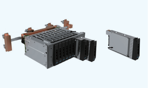
An innovative liquid cooling solution for solid-state drives (SSDs) involves an internal heat pipe-based heatsink that extracts heat from the drive area and transfers it to an external cold plate via thermal pads. This liquid cooling design primarily consists of a solid-state drive module with an integrated heatsink, a cold plate for dissipating heat, a locking mechanism for securing the drive module, and a drive bracket. The locking mechanism ensures long-term contact reliability between the SSD module and the cold plate by providing appropriate preloading force. To facilitate installation within tight spaces, the drive bracket is designed for drawer-style mounting in the server’s depth direction.
Compared to existing liquid cooling attempts in the industry, this solution demonstrates several advancements:
- Supports over 30 hot-swaps without system power interruption.
- Eliminates the risk of damaging thermal interface materials during SSD installation due to the locking mechanism’s design, ensuring long-term contact reliability.
- Requires minimal processing complexity for the liquid cooling solution, utilizing traditional air cooling and CPU cold plate manufacturing processes.
- Features a waterless design between drives, allowing multiple drives to share the same cold plate and reducing the number of connectors, thereby minimizing leakage risks.
- Adaptable to different SSD thicknesses and quantities.
4) Liquid Cooling Design for PCIe/OCP Cards
1.1 PCIe Liquid Cooling Solution
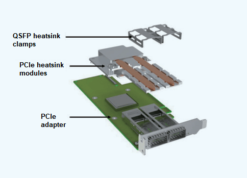
The PCIe card liquid cooling solution builds upon existing air-cooled PCIe cards by developing a heatsink module that makes direct contact with the system cold plate. This design effectively dissipates heat from optical modules and the main chips on PCIe cards. Heat from the optical modules is conducted through heat pipes to the heatsink module on the PCIe card’s main chip. The heatsink module then interfaces with the IO cold plate using an appropriate thermal interface material for efficient heat transfer. The liquid-cooled PCIe card comprises the following components: QSFP heatsink clamps, PCIe chip heatsink modules, and the PCIe card itself. The QSFP heatsink clamps are designed with the right amount of elasticity to ensure proper float during optical module installation, providing a good user experience, preventing damage to optical modules, and achieving the expected cooling performance.
1.2 OCP3.0 Liquid Cooling Solution
The OCP3.0 card liquid cooling solution is similar to PCIe cards. It involves customizing a liquid-cooled heatsink for the OCP3.0 card, which transfers heat from the card’s heat-generating chips to the liquid-cooled heatsink. Ultimately, the heat is dissipated by the heatsink’s contact with the system IO cold plate.
The OCP3.0 liquid cooling module primarily consists of the heatsink module, the OCP3.0 card, and its bracket. Due to space constraints, a spring screw locking mechanism ensures long-term contact reliability between the liquid-cooled OCP3.0 card and the heatsink module after assembly.
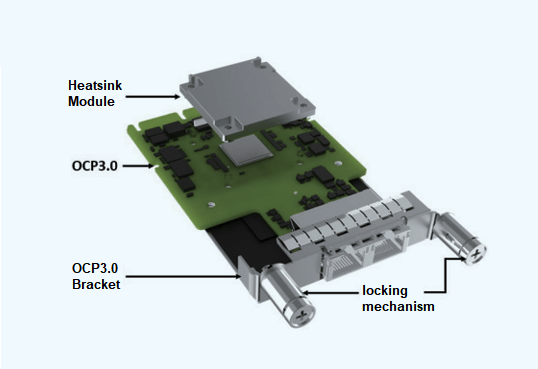
Considerations for ease of maintenance and the OCP3.0 card’s frequent hot-swapping requirements have led to optimizations in the locking mechanism design and the selection of thermal interface materials, enhancing overall reliability and operational convenience.
1.3 IO Cold Plate Solution
The IO cold plate serves as a multifunctional cooling plate. It not only dissipates heat from components within the mainboard’s IO area but also provides cooling for liquid-cooled PCIe cards and OCP3.0 cards.
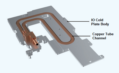
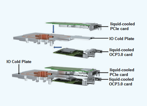
The IO cold plate consists primarily of the IO cold plate body and copper tube channels. The cold plate body is made of aluminum alloy, while the copper tubes play a crucial role in both coolant flow and enhanced heat dissipation. Specific design considerations depend on the mainboard layout and the heat dissipation requirements of individual components. The liquid-cooled heatsink modules on PCIe cards and liquid-cooled OCP3.0 cards make contact with the IO cold plate in the direction indicated by the arrows. Material selection for the coolant flow channels must account for compatibility with the system’s coolant and wetting materials.
This IO cold plate liquid cooling solution addresses multi-dimensional assembly requirements for various components. The hybrid use of copper and aluminum materials resolves material compatibility issues, ensuring effective heat dissipation while reducing cold plate weight by 60% and lowering costs.
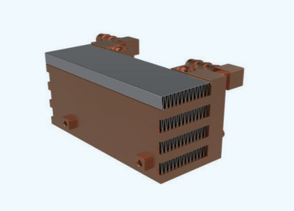
5) Power Supply Cold Plate Design
The power supply unit (PSU) liquid cooling solution builds upon existing air-cooled PSUs by externally attaching an air-liquid heat exchanger to cool the hot air expelled by the PSU fan. This minimizes the system’s preheating impact on the external data center environment.
The PSU rear heat exchanger features a multi-layer structure with overlaid flow channels and fins. The dimensions of the PSU rear heat exchanger must balance heat dissipation requirements, weight, and cost while ensuring compatibility with PSU cable insertion and meeting system cabinet space limitations. The PSU rear heat exchanger is independently assembled onto the node bracket.
This innovative liquid cooling solution for power supplies eliminates the need for developing entirely new liquid-cooled dedicated power supplies. By leveraging its versatility, it significantly shortens development cycles and reduces costs. The solution can adapt flexibly to power supply designs from multiple vendors, resulting in cost savings of over 60% compared to customized liquid-cooled power supplies.
For entire cabinet applications, the power supply liquid cooling approach can employ a centralized air-liquid heat exchanger solution. In this setup, the front and rear doors of the cabinet are sealed, and a centralized air-liquid heat exchanger is positioned at the cabinet’s bottom. This centralized structure replaces the distributed air-liquid heat exchangers typically found in rear-mounted PSUs.
The centralized air-liquid heat exchanger features aluminum corrugated fins with hydrophilic coatings, combined with high heat transfer coefficient copper tubes. It can provide no less than 8 kW of cooling capacity with a temperature difference of 10°C. The heat exchanger’s flow path is optimized for low resistance, allowing it to handle higher flow rates. It incorporates anti-condensation design and comprehensive leak detection to eliminate safety risks. The unique hinge design ensures robust load-bearing capability, while the snap-on connection design facilitates easy installation and maintenance.
Considering that over 95% of the heat generated by a fully liquid-cooled server is dissipated through the cold plate, only a small fraction (less than 5%) requires air-liquid heat exchangers for cooling calculations. Each individual node produces approximately 40-50 W of heat that can be efficiently managed by a centralized air-liquid heat exchanger supporting 8 kW of heat dissipation. This solution can effectively cool more than 150 nodes’ power supplies, all at a significantly lower cost than deploying 150 separate distributed air-liquid heat exchangers.
By implementing this approach, server power supplies remain unmodified, and the heat generated is efficiently collected and exchanged at the rear of the cabinet using the centralized air-liquid heat exchanger. This self-contained circulation within the cabinet ensures no adverse impact on the data center environment, truly achieving the concept of “Rack as a computer.”
Related Products:
-
 10G SFP+ SR 850nm LC Pigtail 1m Immersion Liquid Cooling Optical Transceivers
$20.00
10G SFP+ SR 850nm LC Pigtail 1m Immersion Liquid Cooling Optical Transceivers
$20.00
-
10G SFP+ SR 850nm LC Pigtail 5m Immersion Liquid Cooling Optical Transceivers
$23.00
-
25G SFP28 SR 850nm LC Pigtail 1m Immersion Liquid Cooling Optical Transceivers
$29.00
-
25G SFP28 SR 850nm LC Pigtail 5m Immersion Liquid Cooling Optical Transceivers
$33.00
-
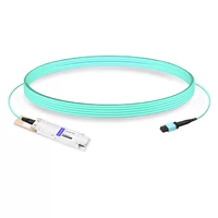
100G QSFP28 SR 850nm MPO Pigtail 1m Immersion Liquid Cooling Optical Transceivers
$86.00
-
100G QSFP28 SR 850nm MPO Pigtail 5m Immersion Liquid Cooling Optical Transceivers
$95.00
-
200G QSFP56 SR4 MPO-12 Female Plug Pigtail 1m Immersion Liquid Cooling Optical Transceivers
$600.00
-
200G QSFP56 SR4 MPO-12 Male Plug Pigtail 3m Immersion Liquid Cooling Optical Transceivers
$620.00
-
Q112-400GF-MPO1M 400G QSFP112 SR4 MPO-12 Female Plug Pigtail 1m Immersion Liquid Cooling Optical Transceivers
$1950.00
-
Q112-400GF-MPO3M 400G QSFP112 SR4 MPO-12 Female Plug Pigtail 3m Immersion Liquid Cooling Optical Transceivers
$1970.00
-
OSFP-400GF-MPO1M 400G OSFP SR4 MPO-12 Female Plug Pigtail 1m Immersion Liquid Cooling Optical Transceivers
$1950.00
-
OSFP-400GF-MPO3M 400G OSFP SR4 MPO-12 Female Plug Pigtail 3m Immersion Liquid Cooling Optical Transceivers
$1970.00
-
OSFP-800G85F-MPO60M 800G OSFP SR8 MPO-12 Female Plug Pigtail 60m Immersion Liquid Cooling Optical Transceivers
$2400.00
-
OSFP-800G85M-MPO5M 800G OSFP SR8 MPO-12 Male Plug Pigtail 5m Immersion Liquid Cooling Optical Transceivers
$2330.00
-
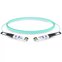
10G SFP+ to SFP+ 850nm 1m Immersion Liquid Cooling Active Optical Cable
$32.00
-
10G SFP+ to SFP+ 850nm 5m Immersion Liquid Cooling Active Optical Cable
$34.00
-
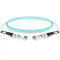
25G SFP28 to SFP28 850nm 1m Immersion Liquid Cooling Active Optical Cable
$52.00
-
25G SFP28 to SFP28 850nm 5m Immersion Liquid Cooling Active Optical Cable
$54.00
-
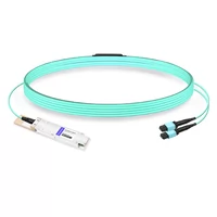
100G QSFP28 to QSFP28 850nm 1m Immersion Liquid Cooling Active Optical Cable
$127.00
-
100G QSFP28 to QSFP28 850nm 5m Immersion Liquid Cooling Active Optical Cable
$132.00