
Benefits of Migrating to 800G Technology
Migrating to 800G technology enables data centers and high-performance computing environments to address the ever-increasing demand for higher bandwidth at a lower cost and with reduced power consumption per gigabit. The primary advantages include:
- Doubled Switching Bandwidth: Compared with 400G per-port systems, transitioning from a 32×400G port configuration to a 32×800G port configuration doubles the bandwidth density—from 12.8 T per rack unit (RU) to 25.6 T per RU.
- Seamless Aggregation of 400G Links: Every 800G port system can be configured as 2×400G. Each 800G device supports two physically independent 400G Ethernet (400GE) links without requiring cable splitting.
- High-Density 400G and Ultra-High-Density 100G: A 32-port, 1RU 800G system can accommodate 64 400GE ports or 256 100GE ports within a single rack unit. The 800G devices are designed to support both 2×400GE and 8×100GE configurations.
- Interoperability with Existing Equipment: The connectivity provided by 800G systems is compatible with current 400G and 100G devices.
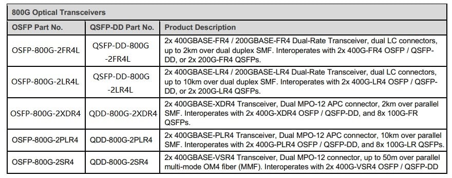
Available 800G Optical Modules and Cables
A comprehensive selection of 800G optical modules is available, including active optical cables (AOC), direct attach copper cables (DAC), and active electrical cables (AEC), all provided in OSFP and QSFP-DD form factors. The accompanying table summarizes the supported 800G connectivity options, and additional media types will be introduced over time.
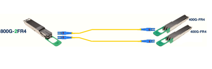
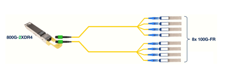
The diagram below illustrates the connectivity between 800G and 2×400G configurations, as well as the decomposition into 8×100G links:

What Form Factors Do 800G and Cables Use?
800G and its associated cables use the same form factors as 400G, namely OSFP and QSFP-DD. Both form factors are supported, and the 800G platform is available in two variants: OSFP and QSFP-DD.
- OSFP: OSFP stands for “Octal Small Form-factor Pluggable.” It is described as an “eight-channel” module because the electrical interface of the OSFP connector is composed of eight electrical channels. When used for 800G, each electrical channel is modulated at 100 Gb/s, providing a total bandwidth of 800 Gb/s.
- QSFP-DD: QSFP-DD stands for “Quad Small Form-factor Pluggable (QSFP) – Double Density (DD).” The QSFP-DD form factor is similar to that of the QSFP, with the addition of a second row of electrical contacts that increases the number of high-speed electrical channels from four (in QSFP) to eight (in QSFP-DD). When applied to 800G, each electrical channel is modulated at 100 Gb/s, which results in a total bandwidth of 800 Gb/s.
Can an OSFP Module Be Inserted into a QSFP-DD Port, or Vice Versa?
No. OSFP and QSFP-DD are two physically distinct form factors. For an OSFP system, OSFP devices and cables must be used; for a QSFP-DD system, QSFP-DD devices and cables are required.
Can an OSFP Module at One End of an 800G Link Interoperate with a QSFP-DD Module at the Other End?
Yes. OSFP and QSFP-DD merely describe the physical form factors of the modules. If the Ethernet media type is the same, OSFP and QSFP-DD modules will be able to interoperate.
Can 400G OSFP/QSFP-DD Modules Be Inserted into 800G OSFP/QSFP-DD Ports?
Yes. When plugged into a switch, the 400G module will be detected and enabled, provided that the physical form factors are compatible (i.e., OSFP modules cannot be inserted into QSFP-DD ports, and vice versa).
Can 800G OSFP/QSFP-DD Optical Modules Be Inserted into 400G OSFP/QSFP-DD Ports?
This is possible only under certain conditions:
Dual-Speed Operation: The 800G module must be capable of operating at half speed (with each electrical channel functioning at 50G PAM-4 instead of 100G PAM-4). The 800G-2XDR4/2PLR4 modules do not support dual-speed operation and cannot be used in 400G ports. However, 800G-2FR4/LR4 optical modules and DAC cables can operate at half speed.
Power and Cooling Requirements: The 400G switch port must be able to support the higher power consumption of the 800G module. Since 800G modules consume more power than 400G modules, they should only be used in 400G platforms that can adequately supply power and dissipate heat for 800G modules. This requirement will restrict the number of 400G platforms capable of accepting 800G modules, even if the modules themselves are operating at a reduced data rate. Please refer to the datasheets of the optical modules and cables for details on power consumption as well as the datasheets for the 400G switch platforms for specific system information.
What Are the Advantages and Disadvantages of Using OSFP Versus QSFP-DD?
QSFP-DD: The QSFP-DD form factor is based on the QSFP form factor with the addition of an extra row of electrical pins. This design ensures strict backward compatibility with 40G and 100G QSFP modules. To dissipate the higher power of 400G modules, QSFP-DD relies on an external heatsink integrated as part of the switch platform—in other words, when a QSFP-DD module is inserted into a QSFP-DD port, the platform must provide a heatsink that contacts the QSFP-DD module and applies sufficient pressure to ensure a low thermal resistance interface.
OSFP: The OSFP form factor was designed from the ground up to achieve optimal performance in both 400G and 800G applications. A key differentiator of OSFP is that its heatsink is integrated into the module enclosure itself. This design ensures the best thermal contact between the power dissipation components and the heatsink, thereby delivering superior thermal performance. Additionally, the surface area of an OSFP module is approximately 50% larger than that of a QSFP-DD module, which enhances the module’s ability to dissipate heat. In the same system, OSFP modules operate at temperatures 5°C to 15°C lower than QSFP-DD modules. This allows for a higher density of devices to be supported, and operating at lower temperatures can lead to improved reliability.
What Do the Suffixes “400G-XDR4 / PLR4, 400G-FR4 / LR4, 800G-2XDR4 / 2PLR4, 400G-VSR4 / 800G-2VSR4 and 800G-2FR4 / 2LR4” Represent?
The letters denote the transmission distance specifications, while the numbers indicate the number of optical channels.
400G-XDR4 and 400G-PLR4:
XDR stands for “Extended Distance DR,” and PLR stands for “Parallel Long Reach.”
XDR4/PLR4 devices use single-mode fiber, covering distances of 2 km and 10 km, respectively. The “4” indicates that there are 4 optical channels.
Each of the 4 optical channels transmits on an independent fiber, requiring a total of 4 fiber pairs (4 fibers for transmit and 4 fibers for receive).
Each channel operates at 100 Gb/s, yielding a total bandwidth of 400G.
The 400G-XDR4/PLR4 interface connects to these 4 pairs of fibers via an MPO-12 connector.
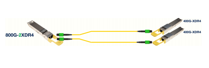
800G-2XDR4 and 800G-2PLR4:
These refer to 2× “400G-XDR4” or 2× “400G-PLR4” interfaces as described above.
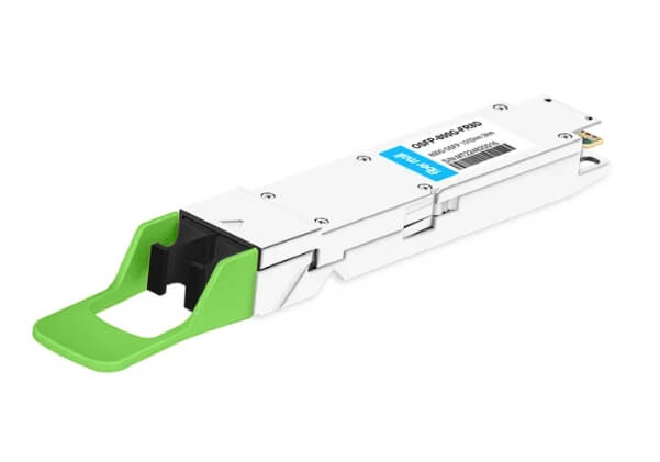
The 800G-2XDR4/2PLR4 modules are equipped with 2 MPO-12 connectors, allowing each 800G optical module to establish 2 physically independent 400G-XDR4/PLR4 links without any cable splitting.
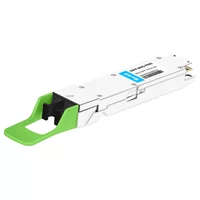
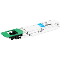
(The accompanying diagram shows the dual MPO-12 connectors used on an OSFP-800G-XDR4 module.)
400G-FR4 / LR4:
FR and LR indicate transmission distances of 2 km and 10 km respectively using single-mode fiber, and the “4” signifies the use of 4 optical channels.
All 4 optical channels from a 400G-FR4/LR4 module are multiplexed onto a single fiber in each direction (one fiber for transmit and one fiber for receive).
Each channel operates at 100 Gb/s, enabling the 400G-FR4/LR4 interface to deliver 400G over a single fiber pair.
These modules use a duplex LC optical connector.
800G-2× FR4 / 800G-2× LR4:
This denotes 2× “400G-FR4” or 2× “400G-LR4” interfaces as explained above.
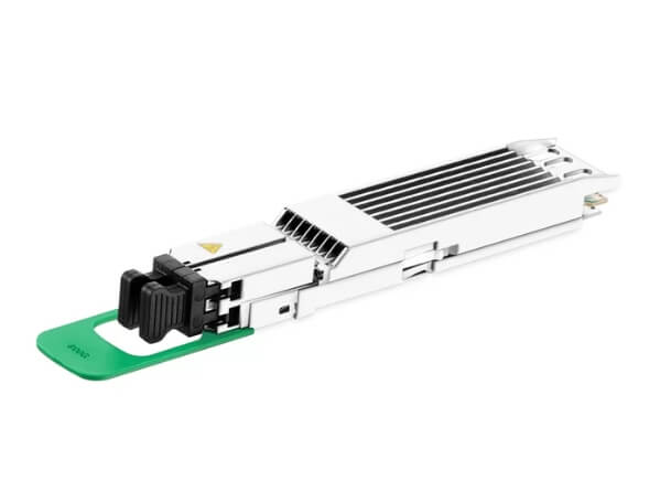
The 800G-2FR4/2LR4 modules have 2 duplex LC connectors, supporting 2 physically independent 400G-FR4/LR4 links from each 800G optical module without the need for cable splitting.
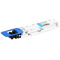
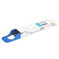
(The diagram below illustrates the dual duplex LC connectors used on an 800G-OSFP-2× FR4 module.)
400G-VSR4:
VSR designates a transmission distance of 50 meters over multimode fiber, with the “4” indicating 4 optical channels.
Each of the 4 channels transmits on its own fiber, requiring a total of 4 fiber pairs.
Each channel operates at 100 Gb/s.
There are two IEEE-defined standards for 100G per wavelength over multimode fiber: 400GBASE-SR4 (for parallel OM4 MMF over 100 m) and 400GBASE-VR4 (for parallel OM4 MMF over 50 m).
The 400G-VSR4 optical modules fully comply with the 400GBASE-VR4 standard and are interoperable with both 400GBASE-SR4 and 400GBASE-VR4 modules within a 50 m distance.
800G-2X VSR4:
This refers to 2 × “400G-VSR4” interfaces, as described above.
The 800G-2VSR4 modules are equipped with 2 MPO-12 APC MMF connectors, enabling each 800G optical module to establish 2 physically independent 400G-VSR4 links without any cable splitting.
Speed and Modulation Format for 800G OSFP/QSFP-DD Modules Compared to 400G OSFP/QSFP-DD Modules
All 800G modules and cables employ 8 electrical channels in each direction (8 transmit channels and 8 receive channels), with each channel operating at a data rate of 100G PAM-4—thus providing a total bandwidth of 800 Gb/s per module.
The optical output from all 800G modules comprises 8 optical wavelengths, with each channel modulated at 100G PAM-4.
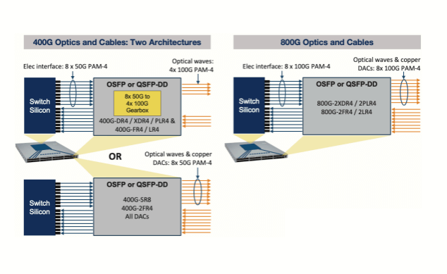
In contrast, all 400G modules and cables use 8 electrical channels per direction (8 transmit channels and 8 receive channels), but each channel operates at a rate of 50G PAM-4, resulting in a total bandwidth of 400 Gb/s per module.
Some 400G optical modules (such as 400G-FR4 and 400G-DR4) employ an 8:4 gearbox to convert the 8×50G PAM-4 electrical signals from the switch chipset into 4×100G PAM-4 optical signals.
Other 400G optical modules (such as 400G-SR8) do not use a gearbox and perform a direct electrical-to-optical conversion to achieve 8×50G PAM-4 optical interfaces.
What are the transmission distances, fiber types, connectors, and optical modulation for each type of 800G optical module?
The table below summarizes the key parameters of the 800G optical modules.
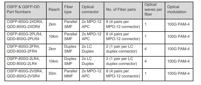
Please note that all of the above optical modules use eight optical channels, with each channel modulated at 100G using PAM-4.
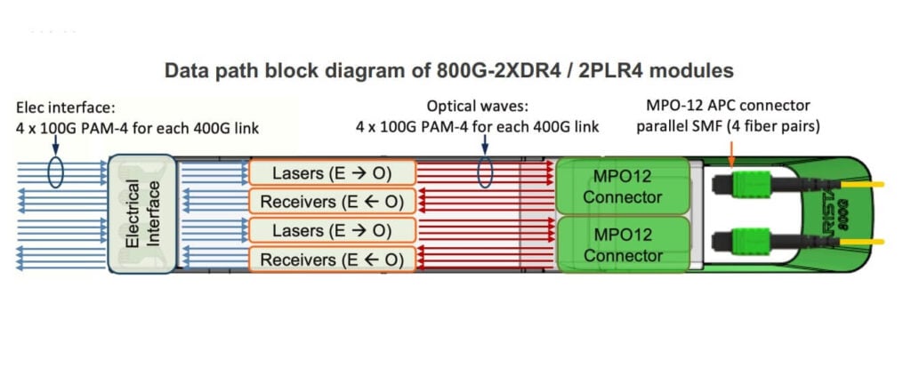
The 800G-2XDR4/2PLR4 optical modules use a total of eight fiber pairs (four pairs per 400G link), with each fiber transmitting a 100G optical wave. The MPO-12 APC single-mode fiber (SMF) connector used in the 800G-2XDR4/PLR4 modules is the same type of fiber and connector used in the 400G-DR4/XDR4/PLR4 and 100G-PSM4/PLRL4 modules. The diagram below shows the data path architecture of the 800G-2XDR4/PLR4 module.
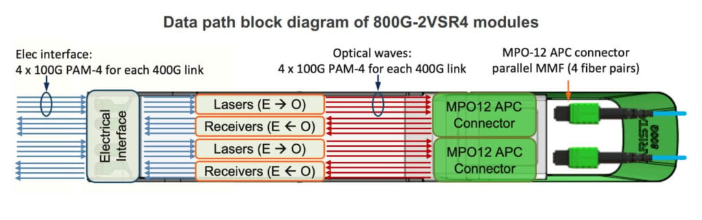
The 800G-OSFP-2X VSR4/800G-QDD-2X VSR4 (as well as OSFP-400G-VSR4/QDD-400G-VSR4) optical modules use MPO-12 APC (8-degree angled physical contact) multimode fiber (MMF) connectors. The APC MMF connector features an angled fiber end-face that helps reduce back-reflection. This is not compatible with the MPO-12 UPC (ultra-physical contact) connectors that are more commonly used in 100G-SR4 and 40G-SR4 MMF optical links. The diagram below shows the data path architecture of the 800G-2X VSR4 module.
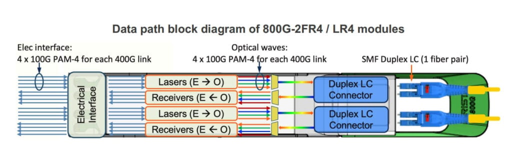
The 800G-2x FR4/2x LR4 optical modules use two pairs of independent fibers (one fiber pair per 400G-FR4/LR4 link), with four different optical wavelengths multiplexed onto each fiber. The diagram below shows the data path architecture of the 800G-2FR4/2LR4 module.
What is the maximum power consumption of 400G OSFP and QSFP–DD optical modules?
The power consumption range for 800G client optical modules is between 16W and 18W per port. Please refer to the optical module data sheets for the power consumption values of each module.
What does it mean when an electrical channel is PAM–4 or NRZ?
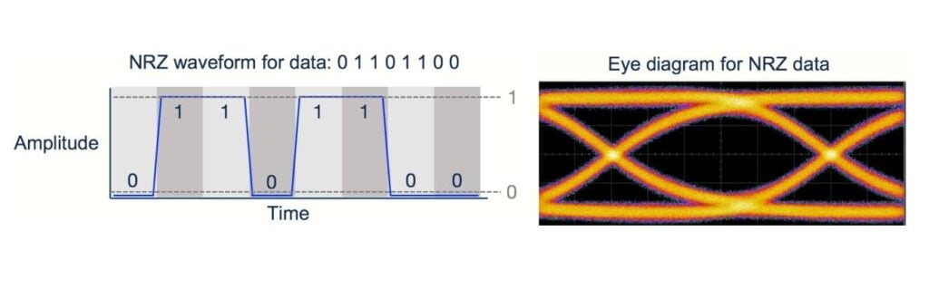
NRZ stands for “non-return to zero” modulation. It describes an electrical or data channel that has only two allowed amplitude levels (or symbols)—one level representing the digital “1” and the other representing the digital “0”. This is the primary modulation scheme used to transmit data at up to 25 Gb/s and is the simplest method for transmitting digital data. The figure below shows an example of an NRZ waveform, along with an “eye diagram” for NRZ data. The eye diagram is simply a way to view the modulation scheme, where each symbol overlaps.
PAM-4 stands for pulse amplitude modulation-4, where the “4” refers to the number of different amplitude levels (or symbols) that carry digital data. In this case, each amplitude level (or symbol) represents two bits of digital data, which enables the PAM-4 waveform to transmit twice the amount of data compared to an NRZ waveform at the same symbol (or “baud”) rate. The figure below shows an example of a PAM-4 waveform, along with an eye diagram for PAM-4 data.
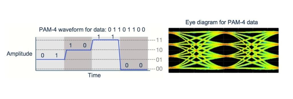
When a signal is referred to as “25Gb/s NRZ” or “25G NRZ”, it means that the signal transmits information using NRZ modulation at a rate of 25 Gbit/s. Similarly, when a signal is called “50G PAM-4” or “100G PAM-4”, it indicates that the signal transmits data at rates of 50 Gbit/s or 100 Gbit/s respectively, using PAM-4 modulation.
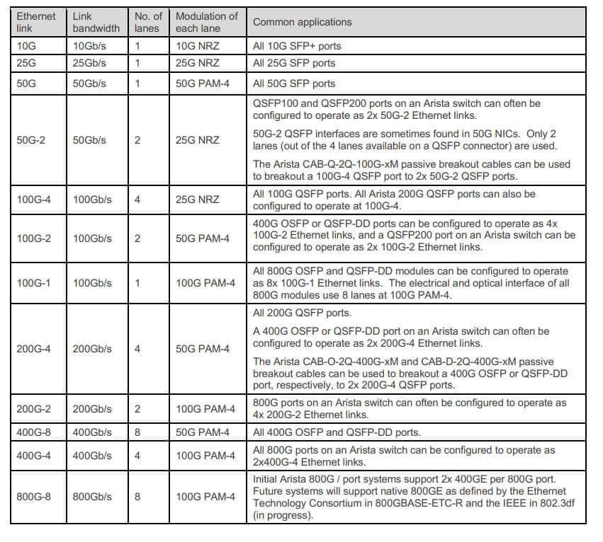
What do the terms 100G–2, 100G–4, 200G–4, 400G–8, 400G–4, and 800G–8 mean?
These terms describe both the bandwidth of an Ethernet link and the number of channels used to achieve that bandwidth. Each front panel port in an Ethernet switch comprises one or more electrical channels, which are used to transmit and receive Ethernet data. For 10G SFP, 25G SFP, or 50G SFP ports, a single electrical channel is used (in each direction) and modulated at 10G, 25G, or 50G respectively. For higher data rates, multiple channels are required. For example, a 100G QSFP port uses four channels, with each channel running at 25 Gb/s, which is why it is also referred to as a “100G-4” interface. The number before the “G” represents the bandwidth of the Ethernet link, while the number following the hyphen indicates the number of data channels required to achieve that bandwidth.
The table below summarizes the terms used to describe common Ethernet speeds, the number of channels required to achieve that bandwidth, and some applications for these interface types.
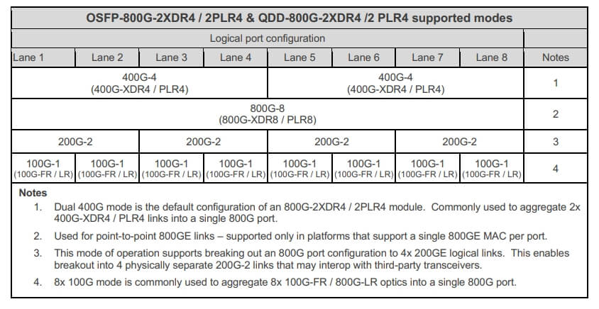
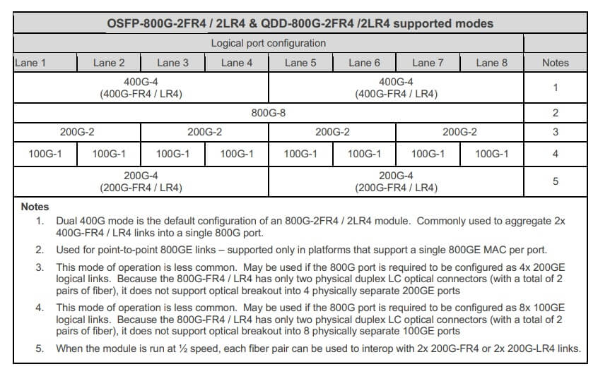
Which Ethernet interconnect datapath applications are supported by 800G optical modules?
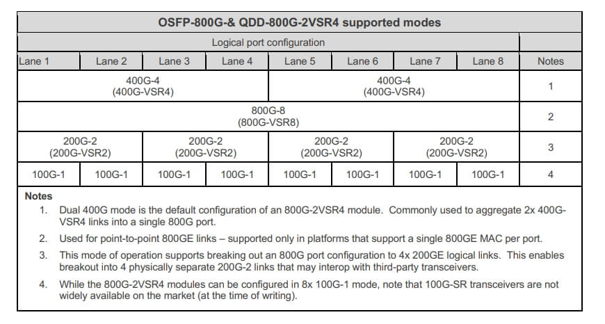
Each 800G optical module and fiber cable can support several different operating modes, as summarized in the table below. The column labels “Channel 1”, “Channel 2”, … “Channel 8” represent the eight-channel electrical interface of an 800G OSFP or QSFP-DD port. The values in the “Lane” column indicate the speed configuration of the 800G switch port, while the text in parentheses represents the corresponding standard.
What is the CLI command for configuring an 800G port to accommodate different speeds and logical interfaces? (Arista Switch)
For 8x 100G-1 operation:
switch(config)#interface Ethernet1/1-8
switch(config-if-Et1/1-8)#speed 100g-1
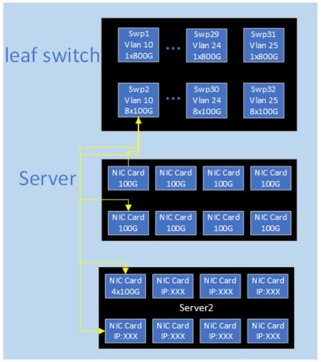
“But when it operates in 8×100G mode, it is treated as eight independent 100G optical module channels, which are encapsulated together only to save space. Consequently, these eight 100G module channels are indeed independent and will not interfere with or affect one another.” The diagram below provides the application note.
For 2x 400G-4 operation:
switch(config)#interface Ethernet1/1,1/5
switch(config-if-Et1/1,1/5)#speed 400g-4
For 4x 200G-2 operation:
switch(config)#interface Ethernet1/1,1/3,1/5,1/7
switch(config-if-Et1/1,1/3,1/5,1/7)#speed 200g-2
For 2x 200G-4 operation (with the 800G port running at half speed):
switch(config)#interface Ethernet1/1,1/5
switch(config-if-Et1/1,1/5)#speed 200g-4
In fiber optic connectors, what do “APC” or PC/UPC mean? Which fiber connectors use APC and which use UPC?
PC and UPC refer to “physical contact” or “ultra-physical contact” fiber connectors. APC stands for “angled physical contact” fiber connectors; in this context, it means the fiber end-face is polished at an 8-degree angle. These terms describe the geometry of the fiber end-face. In PC/UPC fiber connectors, the fiber end-face is “flat.” With APC connectors, the fiber end-face is polished at an angle to reduce back-reflection.
Note: 800G optical modules use MPO interfaces regardless of whether they are applied in single-mode or multimode applications. In order to reduce MPI costs, APC interfaces are used throughout.
Related Products:
-
 Arista OSFP-800G-2SR4 Compatible OSFP 2x400G SR4 PAM4 850nm 100m DOM Dual MPO-12 MMF Optical Transceiver Module
$750.00
Arista OSFP-800G-2SR4 Compatible OSFP 2x400G SR4 PAM4 850nm 100m DOM Dual MPO-12 MMF Optical Transceiver Module
$750.00
-
 Arista OSFP-800G-2PLR4 Compatible OSFP 8x100G LR PAM4 1310nm Dual MPO-12 10km SMF Optical Transceiver Module
$2200.00
Arista OSFP-800G-2PLR4 Compatible OSFP 8x100G LR PAM4 1310nm Dual MPO-12 10km SMF Optical Transceiver Module
$2200.00
-
 Arista OSFP-800G-2XDR4 Compatible OSFP 8x100G FR PAM4 1310nm Dual MPO-12 2km SMF Optical Transceiver Module
$1300.00
Arista OSFP-800G-2XDR4 Compatible OSFP 8x100G FR PAM4 1310nm Dual MPO-12 2km SMF Optical Transceiver Module
$1300.00
-
 Arista OSFP-800G-2LR4 Compatible OSFP 2x400G LR4 PAM4 CWDM4 Dual duplex LC 10km SMF Optical Transceiver Module
$3700.00
Arista OSFP-800G-2LR4 Compatible OSFP 2x400G LR4 PAM4 CWDM4 Dual duplex LC 10km SMF Optical Transceiver Module
$3700.00
-
 Arista OSFP-800G-2FR4 Compatible OSFP 2x400G FR4 PAM4 1310nm 2km DOM Dual Duplex LC SMF Optical Transceiver Module
$1350.00
Arista OSFP-800G-2FR4 Compatible OSFP 2x400G FR4 PAM4 1310nm 2km DOM Dual Duplex LC SMF Optical Transceiver Module
$1350.00
-
 Arista QDD-800G-2LR4 Compatible QSFP-DD 2x400G LR4 PAM4 CWDM4 10km Dual duplex LC SMF FEC Optical Transceiver Module
$4500.00
Arista QDD-800G-2LR4 Compatible QSFP-DD 2x400G LR4 PAM4 CWDM4 10km Dual duplex LC SMF FEC Optical Transceiver Module
$4500.00
-
 Arista QDD-800G-2PLR4 Compatible QSFP-DD 8x100G LR PAM4 1310nm 10km Dual MPO-12 SMF FEC Optical Transceiver Module
$2200.00
Arista QDD-800G-2PLR4 Compatible QSFP-DD 8x100G LR PAM4 1310nm 10km Dual MPO-12 SMF FEC Optical Transceiver Module
$2200.00
-
 Arista QDD-800G-2FR4 Compatible QSFP-DD 2x400G FR4 PAM4 CWDM4 2km DOM Dual duplex LC SMF Optical Transceiver Module
$4000.00
Arista QDD-800G-2FR4 Compatible QSFP-DD 2x400G FR4 PAM4 CWDM4 2km DOM Dual duplex LC SMF Optical Transceiver Module
$4000.00
-
 Arista QDD-800G-2XDR4 Compatible QSFP-DD 8x100G FR/DR8+ PAM4 1310nm 2km DOM Dual MPO-12 SMF Optical Transceiver Module
$2000.00
Arista QDD-800G-2XDR4 Compatible QSFP-DD 8x100G FR/DR8+ PAM4 1310nm 2km DOM Dual MPO-12 SMF Optical Transceiver Module
$2000.00