With the rapid rise of large AI models, modern data centers require faster and higher-bandwidth information transmission technologies to handle the ever-growing data volume. Optical fiber communication, due to its unique high capacity and low loss characteristics, has become the ideal transmission method for modern data centers. The optical transceiver module, as a core component of optical fiber communication systems, is responsible for converting optical and electrical signals. Its performance directly affects the stability and efficiency of the entire communication system. Therefore, FiberMall aims to delve into the fundamental principles of the 800Gbit/s optical transceiver module and validate its performance in practical applications through development and testing.
FiberMall first introduces the basic components of the 800Gbit/s optical transceiver module, including the transmitter unit, receiver unit, management unit, and digital processing chip. It then elaborates on the advanced technologies and design concepts used in the module to ensure stable performance even under high-speed transmission conditions. Subsequently, by developing and testing the 800G OSFP 2xDR4 optical transceiver module, we evaluate whether its key performance indicators meet the expected requirements. Through rigorous development and testing processes, we have found that the 800Gbit/s optical transceiver module meets all the expected performance criteria. Its outstanding performance makes it well-suited for the current environment.
In recent years, ChatGPT has achieved phenomenal popularity. Since its launch, ChatGPT’s user base has proliferated, with over 100 million monthly active users, making it one of the fastest-growing consumer applications in history. ChatGPT’s popularity extends beyond user numbers—it is widely applied and influential. It serves various domains, such as intelligent customer service, virtual assistants, and smart homes, providing convenient and efficient services. Additionally, ChatGPT has garnered attention from many businesses and developers, who widely use it across various fields. Industry consensus recognizes ChatGPT as one of the AI models most likely to pass the Turing test, further enhancing its impact in the field of artificial intelligence.
Against this backdrop, the 800Gbit/s OSFP 2xDR4 optical transceiver module emerges, offering a single-channel 100 Gbit/s parallel transmission solution for the industry. The OSFP 2xDR4 package is an eight-channel, small-form-factor pluggable optical module that achieves higher integration while maintaining performance within the same volume. This module enables higher transmission rates without increasing its physical size.
The 800G OSFP 2xDR4 optical transceiver module offers both single-channel 100Gbit/s parallel transmission and eight-channel transmission. Compared to the four-channel 100Gbit/s transmission of optical modules with the same form factor, it achieves a doubling of the transmission rate. This innovative technology allows the optical module to provide higher data transfer efficiency within the same volume, thereby reducing network bandwidth costs.
The introduction of the 800G OSFP 2xDR4 packaged optical transceiver module provides robust support for the rapid development of cloud computing and big data. With a smaller form factor, higher transmission rate, lower power consumption, and increased reliability, this module meets the demands of modern network communication. Its application will contribute to improved network bandwidth utilization, reduced overall costs, and drive updates and technological innovations in optical fiber communication systems.
Optical Module Design
Module Functional Framework
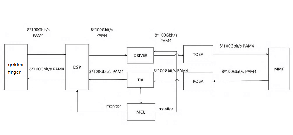
The core components of the 800Gbit/s OSFP 2xDR4 optical transceiver module include the Digital Signal Processing (DSP) chip, Receiving Optical Sub-Assembly (ROSA), Transmitting Optical Sub-Assembly (TOSA), and Microprogrammed Control Unit (MCU). These components work together to achieve high-speed data transmission within the module.
High-Speed Digital Signal Processing Chip
Inside the optical module, the high-performance DSP plays a critical role. It extracts and restores digital clock information from the output signal of the switch, eliminating noise. Additionally, the DSP performs dispersion compensation and nonlinear interference removal on the received optical signal to ensure accurate and undistorted data. This component also participates in the communication process between the electrical and optical interfaces of the optical module, facilitating data conversion and operations. At the receiver end, the DSP features adaptive linear equalization, compensating for amplitude differences based on signal frequency variations, further enhancing data transmission efficiency and quality.
Digital Signal Processing (DSP) technology plays a crucial role in optical modules. It is closely connected not only to the “Golden Finger”, which serves as the contact point for data transmission but also to key components like the driver and transimpedance amplifier (TIA). Together, they ensure the efficient operation of optical modules.
Signal Conversion and Processing:
DSP technology primarily handles signal conversion and processing within optical modules. As optical signals pass through the module, DSP converts analog signals to digital format and performs necessary processing to maintain signal quality and integrity. High-quality signals are essential for accurate and reliable data transmission.
Golden Finger Connection:
The connection between DSP and the Golden Finger is critical for data transmission. The Golden Finger acts as a physical contact point, transferring electrical signals from the optical module to other devices (such as computers or network equipment). DSP ensures minimal errors and interference in the signals transmitted via the Golden Finger, enhancing data transfer efficiency and stability.
Driver Collaboration:
DSP’s connection with the driver ensures effective signal transmission from the optical module. The driver controls the laser and adjusts its intensity and frequency based on DSP instructions, adapting to various transmission requirements. This close collaboration optimizes the module’s sending performance, improving signal quality and transmission distance.
TIA Link for Reception:
The connection between DSP and the Transimpedance Amplifier (TIA) is crucial for signal processing on the receiving end. The TIA amplifies optical signals received from the fiber and converts them into electrical signals. DSP further processes and analyzes the TIA’s output to ensure accurate data reception.
Additionally, the impact of line filtering on low-frequency signals can disrupt electronic information transmission. When current signals experience sudden changes, the line’s low-frequency filtering may weaken the voltage difference received by DSP, approaching the decision threshold. This can lead to higher error rates and even network service interruptions. To address this, DSP employs pre-emphasis techniques, ensuring sufficient decision thresholds in the switch-side signal judgment to prevent misjudgments.
Emission Unit
In the optical emission unit, the laser driver chip acts as an electrical switch, providing the threshold current required for the laser chip’s normal operation. To ensure stable laser chip performance, the driver current must exceed the threshold current.
Semiconductor characteristics dictate that as temperature rises, the laser chip’s threshold current gradually increases. Therefore, to maintain proper laser chip operation at higher temperatures, the driver current supplied to the laser driver chip needs to be adjusted accordingly.
Real-time temperature monitoring using an analog-to-digital converter in the monitoring unit.
Adjusting the temperature compensation circuit to increase the laser driver chip’s drive current, ensuring stable output optical power. This approach ensures laser chip stability even in varying temperatures, enhancing the overall efficiency and stability of the optical emission unit.
Receiver Unit
The interface of the optical transceiver module primarily consists of a photosensitive sensor (pin), driver components, and peripheral circuits. The operation mechanism of the photosensitive sensor involves generating current while minimizing input noise. The strength of the current signal depends on the detector’s response rate and coupling techniques.
Monitoring Unit
The built-in MCU (Microcontroller Unit) in the optical transceiver module is responsible for monitoring and managing the module’s operational status. Utilizing the I2C bus protocol, the MCU can read from and write to registers of optoelectronic chips, adjusting and monitoring the state of each chip. Additionally, the MCU incorporates an analog-to-digital converter to collect and analyze status information from various internal chips within the module.
The monitoring and management unit ensures stable operation of the optical transceiver module. By continuously monitoring key parameters, it ensures that the module operates optimally, thereby maintaining the stability and reliability of the entire communication system.
The internal structure of the optical module is depicted in the figure below.
Optical Module Test Results Analysis
Test Environment
Performance testing of the optical transceiver module focuses mainly on the transmitter and receiver units. At the transmitter end, the optical signal is directly connected to an eye diagram instrument via optical fiber. At the receiver end, we use a reference light source (Gold Standard) that generates optical signals across eight channels. These signals, after passing through an adjustable optical attenuator, are directed into the receiving end of the module we want to test. We adjust the attenuator settings as needed to control the optical intensity reaching the target module’s receiver. Once an error rate of 2.4E-4 is detected, the corresponding optical intensity serves as our sensitivity metric.
Transmitter Testing Parameters and Results
Transmitter testing includes several aspects: average optical power, extinction ratio, linearity, and transmitter dispersion eye closure (TDECQ).
Average Optical Power: This parameter represents the average optical power emitted by the optical module. It is typically measured in milliwatts (mW), microwatts (μW), or decibel milliwatts (dBm). Average optical power reflects signal strength and is a critical performance metric for optical modules.
Extinction Ratio: The extinction ratio refers to the ratio of optical power between transmitting “1” and “0” signals. Ideally, the extinction ratio should be infinite, indicating a significant power difference between the two signals, and allowing the receiver to distinguish them easily. Poor extinction ratio can lead to data demodulation errors.
Transmitter Dispersion Eye Closure (TDECQ): This parameter relates to the dispersion effect on optical signals during transmission. Dispersion causes optical pulses to spread at the receiver end, reducing signal clarity and readability. TDECQ describes the ability and performance of eye closure under different dispersion conditions. A well-behaved TDECQ ensures signal quality remains high during long-distance transmission. These parameters are crucial for evaluating optical module performance and quality, ensuring reliable and efficient data transmission. Accurate measurement and assessment of these parameters during testing help meet design requirements and application needs.
According to the IEEE802.3df_D3p1 protocol specifications, when the module’s single-channel rate is set to 53.125 GBd/s, the optical eye diagrams at the transmitter end should meet the following criteria:
Transmitter Dispersion Eye Closure Quaternary (TDECQ) should be less than 3.4 dB.
The extinction ratio should be greater than 3.5 dB.
Average optical power should fall within the range of 2.9 to 3.4 dBm.
During the experiment, we tested a single optical eye diagram at the transmitter end using a four-bit short-intensity random sequence code as the standard configuration for the error analyzer. The module’s temperature was maintained at 0°C, 25°C, and 70°C to assess performance under different conditions. Detailed data for each channel’s optical eye diagrams at varying temperatures are provided in Tables 1, 2, and 3.
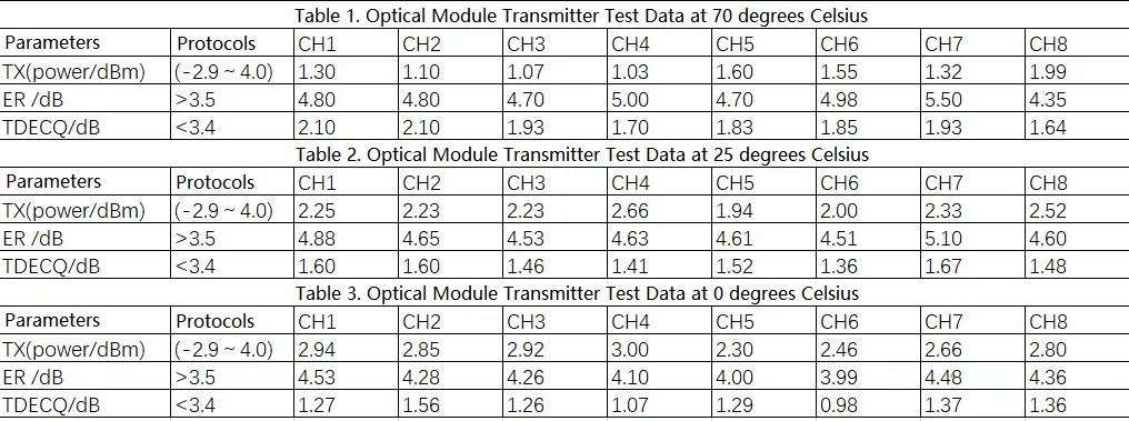
Based on these parameters, we confirmed that the optical module’s transmitter eye diagram parameters comply with contractual temperature requirements. The measured results are shown in Tables 1, 2, and 3. Furthermore, all parameters for this optical module currently meet industry protocol requirements with a significant margin, indicating superior product performance.
Receiver Testing Results
According to the IEEE802.3df_D3p1 standard, if the module achieves a single-channel speed of 53.125 GBd/s, the received signal must be below -4.3 dBm to meet sensitivity requirements. We assessed the receiver sensitivity of the test module using well-characterized optical transceivers and an external light source with good optical eye diagrams.
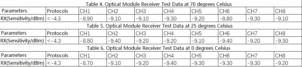
By adjusting the variable optical attenuator to control the output optical signal power, we verified that the 800 Gbit/s OSFP 2xDR4 optical module’s eight channels meet the protocol requirements for sensitivity across three temperature conditions, with performance parameters having ample margin compared to industry norms.
Summary
As AI applications like ChatGPT continue to grow, data transmission demands are increasing rapidly. Optical modules play an increasingly critical role in high-speed optical communication networks within data centers. These modules are key components for achieving efficient data transfer, and their performance and reliability are crucial for data center operations.
Firstly, as data centers continue to expand in scale and data traffic grows, the demand for optical modules is steadily increasing. The performance metrics of optical modules, such as transmission rate, distance, and reliability, significantly impact the overall performance of data centers. Consequently, with the rising need for high-speed, high-capacity data transmission in modern data centers, the performance requirements for optical modules are also becoming more stringent.
Secondly, as AI applications advance, the energy efficiency requirements for optical modules are also increasing. The growing computational power of AI leads to higher energy consumption, prompting manufacturers to seek energy-saving solutions. Optical modules, being an efficient and low-energy data transmission method, offer significant advantages in reducing data center energy consumption. Therefore, as AI applications become more widespread, the adoption of optical modules in data centers is expected to expand further.
In summary, with the success of AI applications like ChatGPT, optical modules are poised for broader development prospects in high-speed optical communication networks within data centers. As data transmission demands continue to rise and technology advances, the application scope and performance requirements of optical modules will continue to evolve.
The 800 Gbit/s optical transceiver module plays a crucial role in high-speed optical communication equipment for data centers, cloud computing, and network communication. Here are some key features of the 800 Gbit/s optical transceiver module:
High-Speed Data Transmission Capability: The 800 Gbit/s optical transceiver module can provide data transmission rates of up to 800 Gbit/s, a significant improvement over existing 400 Gbit/s and 100 Gbit/s modules. This meets the growing demands for high bandwidth and large-scale data transmission in modern data centers.
Advanced Modulation Techniques: The 800 Gbit/s optical module employs PAM4 (Pulse Amplitude Modulation) technology, which transmits four different voltage levels within one signal cycle, achieving higher data transmission rates and efficiency.
Versatile Application Scenarios: The 800 Gbit/s optical module is suitable for various application scenarios, including short-range (SR), medium-range (DR/FR/LR), and long-range (ER/ZR) transmissions, meeting the interconnection needs of different network architectures and data centers.
Low-Power Design: Energy efficiency is considered during the design of the 800 Gbit/s optical module, utilizing low-power optoelectronic devices and circuit designs to reduce overall energy consumption and improve efficiency.
High Integration and Compact Size: The module adopts a high integration design, such as Chip on Board (COB) technology, integrating multiple optoelectronic devices into a small-sized module for ease of deployment.
Robust Forward Error Correction (FEC) Capability: To ensure reliable data transmission, the 800 Gbit/s optical module typically includes powerful FEC algorithms, such as KP4 FEC, enhancing receiver sensitivity and reducing bit error rates (BER).
Compatibility and Standardization: The 800 Gbit/s optical module adheres to industry standards like QSFP-DD and OSFP MSA, ensuring compatibility and interoperability with other devices while promoting industry health.
Support for Various Signals and Testing Functions: The module supports multiple signal formats, such as PAM4 or NRZ, and includes features like loopback, breakout, PRBS, and SNR testing for network debugging and maintenance.
These features collectively make the 800 Gbit/s optical transceiver module a critical technology to meet future demands in data centers and high-speed networks.
Currently, optical technology’s global impact is increasingly significant, and research and development of optical devices are undergoing rapid progress and transformation. The field of optical module development is also experiencing rapid growth.
The rapid advancement of optical module technology has seen data transmission rates leap from 200 Gbit/s to 400 Gbit/s and is now progressing toward 800 Gbit/s. This rapid development brings unprecedented efficiency and convenience to data centers. As a core component built upon 800 Gbit/s optical communication networks, the 800 Gbit/s optical module’s importance in data center optical communication systems cannot be overlooked. Detailed explanations of its fundamental construction and operation principles, along with empirical testing, demonstrate that it fully meets relevant technical specifications for effective operation in an 800 Gbit/s optical communication network environment.
Our proposed OSFP 2xDR4-type 800 Gbit/s optical module exhibits clear advantages in terms of economic benefits and energy consumption. With ongoing developments in optical component manufacturing processes and communication technology, this module is expected to have even broader market potential in large-scale data center fiber communication networks in the future.