
The QSFP28 100G BiDi transceiver module is gaining significance in the telecommunications environment as it allows the networks to be more efficient and have an elevated capacity. In this way, it applies a more advanced optical approach to achieve data transmission in both directions by using only one optical fiber, increasing the present bandwidth by up to 100% without needing additional physical infrastructure. This article investigates the specifications, principles, and intended uses of the QSFP28 100G BiDi transceiver to provide informed insights into the transceiver’s structure and its implications for future networking. It’s our goal to furnish networking practitioners with this knowledge to enable them to exploit the advantages and ways of integrating this particular transceiver in their networking setups.
What is a QSFP28 100G BiDi Transceiver?
Understanding the QSFP28 Transceiver
The QSFP28 transceiver is a small-size, high-capacity unit that can achieve a data rate of 100 Gbps. Its standard form factor makes it easier to use with several networking devices and enables easy adoption in the current systems. The QSFP28 has four transmit and receive channels so that the information can be packed into fast optical signals, facilitating long-distance communication. It can span different types of mediums, such as multimode and single-mode optical fibers, which can be used in various configurations within the network without sacrificing performance or scalability. This modular configuration improves the bandwidth limitation situation and helps reduce complexities in managing and upgrading the networks.
How 100G BiDi Technology Works
A single optical fiber can be used for simultaneous transmission and reception of the data using 100G BiDi Technology, thereby reducing the footprints of the fiber optic cabling. This technology uses full duplex communication over a fiber since two (2) separate wavelengths are utilized simultaneously, for instance, 1310 nm for sending and 1550 nm for receiving. Transceiver modules are then designed with modern optics that allow them to precisely modulate and demodulate light signals. Such characteristics determine the efficiency and economy of the technology, making it suitable for the construction of contemporary data center interconnects and long-distance broadband communication network applications, improving the overall performance of the network while preserving signal fidelity.
The Role of LC Connectors in Optical Transceivers
LC connectors stand for Lucent Connectors. These are essential parts of optical transceivers for communication, establishing a connection with the fiber optic. Their small size facilitates the perfection of high-density fitting and is most suitable for space-limited areas like data and telecommunication rooms. LC connectors have a pull and push feature, increasing the column of LC connectors with straightforward insertion and extraction processes. They focus on making systems that operate on single-mode and multi-mode fibers. The physical structure of LC connectors allows the fiber inside to be held in a position that stops excessive light losses. This leads to an overall higher quality transmission. In optical networking applications, reliability and precision become key components. This need is satisfied by the use of LC connectors.
Key Features of 100G BiDi QSFP28 Modules
Advantages of PAM4 Modulation in QSFP28 Modules
PAM4 (Pulse Amplitude Modulation with four levels) modulation offers many benefits, making it highly suitable for use with QSFP28 modules, chiefly in data transmission efficiency and capacity. First and foremost, PAM4 makes it possible to send two bits of information instead of one bit per symbol, meaning there’s effectively a doubling of the data rate without an increase in the bandwidth. This feature is helpful, especially for high-speed applications like enabling 100G over the existing infrastructure and minimizing the frequency of upgrades while enhancing performance with FEC features.
Also, adopting the PAM4 modulation technique helps in reducing power consumption. The fewer transmission channels required to achieve high data rates, the less power is consumed, necessary to make energy-efficient networking products. Also, better bandwidth utilization is possible with PAM4 modulation due to improved spectral efficiency. Therefore, the network handles operations at higher throughput levels without compromising signal integrity. Because of PAM40, QSFP28 modules provide inexpensive, scalable deployment within the data centers and long-haul communications, including using a 40km fiber optical link.
In conclusion, PAM4 modulation helps to reduce the latter two parameters to the former; that is, data rate improves while power consumption and bandwidth efficiency improve, thus emerging at the forefront of modern-day optical networks’ needs.
Importance of DOM in Optical Transceivers
Digital optical monitoring (DOM) is emphasized in operating and managing optical transceivers, as it also provides valuable and essential diagnostic information. This information improves the reliability and effectiveness of the networks. The main benefit of DOM is that it can carry out real-time measurements of the device’s temperature, voltage, and optical power level. Real-time supervision plays a vital role in spotting the signs of failure before their actual occurrence, hence performing predictive maintenance.
Moreover, the information from DOM helps make more accurate planning and distribution of resources in the network by enabling the evaluation of performance parameters of the optical links. Based on the data received from DOM, the configurations of the optical networks could be boosted for optimum efficiency and usage of the network capabilities. Such functionality is especially useful in high-density data-cabinet facilities, where effectively managing many links is critical to preserving performance levels.
Simply put, using DOM for optical transceivers improves their work, prevents interruptions, and contributes to the well-being of networks. All components are essential to today’s optical networks.
Exploring Single Lambda Technology
The technology of Single Lambda is one of the essential solutions in the field of optical network advancement as it enables higher bandwidth and improved performance levels by sending information over a single light wavelength. This, in turn, simplifies the transceiver design by minimizing the number of building blocks integrated into them, hence providing cost and power effectiveness. The rate that can be provided with the current Single Lambda approaches is 400G and beyond, thanks to using PAM4 modulation formats for increasing enhancement.
As the growth of cloud service providers and data centers creates an increasing bandwidth requirement, Single Lambda solutions are quickly being embraced by more and more industry leaders to meet it. This technology is beneficial for long-haul and metropolitan applications as it makes it possible to upgrade networks without making extensive changes to the existing network infrastructure; besides, reducing the number of lambdas to a single means that resources will be used more efficiently, enhancing the entire network’s performance.
How to Deploy 100G BiDi Modules in Your Data Center
Setting Up Simplex LC Connections
It is imperative to understand that scaffolding Simplex LC connections must be done in a prescribed manner to achieve optimal usage and reliability. The following steps outline the process:
- Preparation: Collect all necessary tools: Simplex LC connectors, optimum spatially compatible optical cables, and cleaning equipment. It is also essential to keep the working environment dry and free of dust and dirt since these contaminants will only work to worsen the connection.
- Cable Stripping: With the help of a microphone or other precision tools, the cable stripper releases the outer day casing not to damage the fractionated fiber strand. It is advisable to strip only as much as is necessary to butt the connector.
- Fiber Cleaving: After removing the fiber from the connector using a fiber cleaver, the end of the fiber should be cross-sectional. A clean cut will enhance the connection by reducing optical losses. The cut length should conform to the LC connector specifications.
- Connector Assembly: Once complete, the Simplex LC connector is fully engaged with the cleaved fiber. When the fiber is housed within a connector, most connectors incorporate some mechanism to hold the fiber in place. Read the manual of the specific device for such assembly procedures.
- Testing: After making the Simplex LC connection, continuity testing is done by an optical power meter or visual fault locator. This assures the connection’s proper functioning while ensuring no significant losses.
- Final Inspection: The connector’s end face should be visually examined for roughness or dirt contamination. Clean the end face of the male or female connector with appropriate optical cleaning materials if needed.
Following these essential steps, users can use Simplex LC connections effectively, with improved performance and reliability in optical network application systems.
Considerations for 10km and 20km Deployments
Several factors need to be examined and addressed thoroughly to make deploying optical networking at distances of 10km and 20 km efficient and trustworthy.
- Cable Type and Quality: Single-mode fiber optic cables must be used for distance measures as they have lower attenuation than multimode cables. Choosing the proper cables of good quality with the required specifications helps reduce long-distance transmission signal losses.
- Signal Strength and Transceiver Specifications: Compatible and distance-oriented optical transceivers must be in place during use. For 10km deployments, SFP+ with a minimum output of -5dBm or LC connectors are recommended. However, for 20km, the standard output of the transceivers must remain in the range of -2 dBm to uphold the signal’s integrity.
- Dispersion management: Furthermore, at long haul distances, signal quality may deteriorate due to chromatic dispersion. Dispersion compensation or special fibers to mitigate the negative impacts may be an option for both 10km and 20km connections.
- Environmental Factors: Planning should also consider environmental factors such as temperature, moisture content, and mechanical stresses. The correct use of outdoor-rated cables and proper storage and installation methods can mitigate these risks.
By overcoming these hurdles, network engineers can improve the performance and sustainability of optical networks within 10km and 20km deployments.
Ensuring Compliant Installations
Proper and compliant optical network installations are necessary to promote practical day-to-day activities and comply with industry standards. Compliance is obeying federal rules, the criteria set by a manufacturer, and safety and performance guidelines.
- Compliance with Industry Standards: Subscribe to standards developed by the Telecommunications Industry Association (TIA) and the Institute of Electrical and Electronics Engineers (IEEE) to ensure that all installations are capable of performance and safety workmanship.
- Provision of Adequate Documentation: Develop proper documentation that includes installation procedure details, component details, and test results performed. This maintains installation procedures’ legal and regulatory compliance to enhance responsibility and traceability.
- Employing Staff, including Training and Certification: Hire only certified people to work on fiber optic cables and their installation. Continued education guarantees that people will not forget new technology, standards, and regulations.
- Looking for Irregular Operations: Carry out planned internal and external checks of installations at reasonable intervals to ascertain that installations are still honest to the requirements of issued documents and legal instruments. De-risking is possible, thus improving the network’s reliability by acting on problematic areas/applications well in time.
Inabilities to adhere to these guidelines makes it hard for organizations to improve the compliance and the reliability of the optical network installations, hence hindering attaining the best performance possible out of the system and diminishing the hazards of operational failure occurrences.
How Does the 100G QSFP28 BiDi Transceiver Compare?

Comparing QSFP28 with Other Optics
The 100G QSFP28 BiDi optical transceiver has a higher bandwidth and scalability when compared to other optical transceiver modules, such as 100G SFP28 or 40G QSFP, which are claimed to be using this technology. Key differences include:
- Data Rate and Capacity: Unlike other transceivers, the maximum data rate supported by the QSFP28 transceiver is 100 Gbps using a single optical fiber. This incorporation of advanced modulation that includes PAM4 is a significant improvement over the SFP28, which typically provides 25 Gbps per channel, whereas the 40G QSFP+ offers 40 Gbps using four channels of 10 Gbps each.
- Form Factor and Density: Compared to SFP28, the QSFP28 design is space efficient and delivers more ports in the networking equipment. This is important in data centers due to the limited area available as more connections are realized per area than the SFP28 or even 40G QSFP+ sections can accommodate.
- Cost Efficiency: Instead of 25 Gbps SFP28 transceivers or four 10G links with a QSFP4 using five transceivers, the QSFP28 can provide transport at 100 Gbps over a single fiber link, which reduces the cost and complexity of infrastructure. This makes it more cost-effective for high-capacity networks.
To summarise, the 100G QSFP28 BiDi transceiver is remarkable for its high data bandwidth, space efficiency, and affordability, which suits the needs of many contemporary data centers and high-speed networks.
The Benefits of Single-Mode Fiber (SMF)
This SMF configuration has advantages that make it the most suitable solution for international telecommunication and data transmission networking.
- Higher Efficiency Bandwidth Usage: The central core diameter of 8 – 10 microns, compared to the regular 50 ęm, lets the distances over which a specific signal can be transmitted increase without a marked degree of signal loss. This means a bigger bandwidth that can take more data traffic per wavelength.
- Increased Reach: Generally, SMF can be used for distances greater than 40 kilometers without signal boosters or repeaters. This is especially true for installations spread over a large geographical area, such as metro networks and long-distance communications.
- Low Signal Loss: Due to the SMF construction, few modes are used, which decreases the modal dispersion. Thus, further distance can be achieved with fewer signal errors, and data can also be sent without packet loss.
- Advantage for Large Scale Deployment: While SMF should be more expensive than MMF in the first implementation cost, the running cost is quite often cheaper. This effectiveness is due to the minimal use of repeaters and amplifiers in large fiber optic communications networks.
Subsequently, the remarkable attributes of Single-Mode Fiber make it the best option in greater distance and capacity performance applications, satisfying contemporary data communication requirements.
Compatibility with Cisco Networks
The network’s infrastructure and design incorporate more Single-Mode Fiber (SMF) links, compatible with Cisco networks as Cisco networks are more robust, reliable, and high-performing. Cisco brand has several optical transceivers for SMF applications, which range over 40km, such as SFP, SFP+, and SFP28 modules. Overutilizing or underutilizing SMF cable infrastructure within Cisco’s architecture is cost-efficient as it effectively minimizes bandwidth costs during long-haul data communications. In addition, SNMP-compatible switching and routing modules from Cisco are also designed with the functions for operating SMF networks, aiding organizations in using advanced networks for tasks like cloud computing, video conferencing, and real-time data processing, among other applications. The incorporation of the two improves not only network efficiency but also operation effectiveness.
Frequently Asked Questions About QSFP28 Transceivers
Why Choose 100G BiDi?
Using 100G BiDi (Bidirectional) transceivers has vital benefits, making it a worthy buy for data centers and high-speed network applications. Firstly, transceivers 100G BiDi adopt Bi-Di technology that enables bi-directional data transmission in and out of an optical fiber using two wavelengths of light. This substantially reduces the fiber quantity used, translating into material and labor cost savings. Secondly, BiDi modules being small in size enables higher density applications, which allows more connections in small areas, which is an essential aspect of today’s networks. In addition, they do not require the replacement of specific network devices as they have 100G performance and do not require mode upgrades and reconfiguration of system overlong cable length for 100G Ethernet. The proposition of high efficiency, compactness, and performance has made 100G BiDi transceivers the best. It is ideal for those companies looking to upgrade their network facilities.
What is QSFP28 MSA and Why is it Important?
The QSFP28 MSA is a standard issued in general collaboration among several manufacturers to develop the standard for 100G QSFP28 transceivers. This document not only prescribes the physical and electrical parameters but also lays down the inter-operational functional and operational parameters required from the products of different manufacturers. Thus, its cardinal significance lies in addressing the challenge of vendor-lock-in situations and ensuring that high-speed networks run seamlessly. Organizations can utilize parts from other manufacturers without worrying that one manufacturer’s parts can only integrate with those of the same manufacturer. The efficient adherence to MSA policies may also lessen obsolescence issues and thus offer adequate protection for the investment of data centers and enterprises as they move towards faster networking technologies.
How to Utilize Digital Diagnostics Functions
The digital diagnostics functions are necessary for supervising and operating the optical transceiver design, and QSFP28 modules are included. With these functionalities, the following actions must be undertaken:
- Link into the Diagnostics Interface: Many transceivers today can perform operations with digital diagnostics based on the SFF-8472 standard. Connect to the host system or network management software, connected with the 100G BiDi QSFP28 optical transceiver or its module, and download the diagnostics data. This usually involves using a command line or Graphical User Interface to read digital diagnostic monitoring (DDM) data.
- Focus on Parameters of Interest: Critical parameters for diagnosis include temperature, voltage, laser bias current, transmit optical power, and receive optical power. These parameters should be taken periodically in case the system foresees any risk of failure in the system being embraced.
- Put up Alerts and Diagnostics Logs: Configured an alert if an out-of-range parameter is detected so that someone can attend to the problem. Also, keep a record of any diagnostic data for the system, as it promotes solving issues in the future.
- Calibration and Testing: The diagnostic functions can also be employed in the system’s first set-up and when performing periodical maintenance checks to adjust the system. Checking the performance of devices with simulated load conditions helps detect the transceivers’ performance maintained within the ideal operation conditions.
- Keeping Firmware Up to Date: The firmware of the transceiver and host equipment Print Servers must be updated. Vendors often offer new diagnostic capabilities and other functionalities as upgrades.
Observing these guidelines can help network administrators utilize digital diagnostics functions to maintain the reliability and efficiency of networking devices.
Reference Sources
Frequently Asked Questions (FAQs)
Q: What is a QSFP28 100G BiDi transceiver module?
A: The QSFP28 100G BiDi transceiver module is an electro-optical transceiver module targeted at 100G Ethernet applications over single-mode fiber (SMF) via Bidirectional (BiDi) transmission over fiber. The transceiver supports simultaneous information transmission to and from along a single fiber, thereby saving fiber optic cable resources and enhancing high-speed optical information transmission.
Q: How does the QSFP28 100G BiDi transceiver module fashion?
A: The QSFP28 100G BiDi transceiver module uses dual wavelengths on a single fiber in one direction to send and in the opposite direction to receive information. The wavelengths are used at 850nm and 900 nm. This type of transmission is bidirectional, and therefore, it minimizes the usage of additional fibers, making the overall structure of the networking system easier and less expensive.
Q: Is the QSFP28 100G BiDi transceiver module warranty protected?
A: Yes, the QSFP28 100G BiDi transceiver module would be an interchangeable device that is compliant with the QSFP28 annex C MSA. Its compatibility with other MSA-compliant devices guarantees its usability across several network frameworks, including Cisco systems.
Q: What can the QSFP28 100G BiDi transceiver module be used for?
A: The QSFP28 100G BiDi transceiver module is useful in data centers, high-performance computing interconnects, and high-end communications enterprise networks. It carries ratings such as 100 G Ethernet and is well suited in situations where fiber is often lacking.
Q: What is the maximum range that a QSFP28 100G BiDi transceiver module is designed to transmit?
A: The QSFP28 100G BiDi transceiver module can support transmission distances of up to 10km when DDM is used over a single-mode fiber (SMF) transmission system. This is ideal for medium—and long-distance data communication in metropolitan and campus area networks.
Q: What connector type is used with the QSFP28 100G BiDi transceiver module?
A: The range of wavelengths of 850-910 nm is typical in applications utilizing the QSFP28 100G BiDi transceiver module, which generally uses a simplex LC connector for single-mode fiber (SMF) applications. Simplex LC connector exhibits ease of expression and secure connection, promoting the practical design of transmission networks.
Q: Is the QSFP28 100G BiDi transceiver module suitable for deployment in new and existing network infrastructure?
A: Yes, the QSFP28 100G BiDi transceiver module can work with the deployed node of the existing network so that it can be used in new deployments very easily within the context of any existing infrastructure. It can transmit data in both directions, easily replacing installed Gigabit Ethernet without expending cabling resources.
Q: What are the QSFP28 100G BiDi transceiver module’s benefits for conventional transceivers?
A: There are many benefits of using the QSFP28 100G BiDi transceiver module over line transceivers, including the amount of fiber used, its cheapness, and easy fiber management. Its amazing feature of using bidirectional transmission enables fast interaction over a single fiber, thus avoiding differential usage of cabling in a network.
Q: Can the QSFP28 100G BiDi transceiver module be used in active optical networks?
A: Yes, the 100G BiDi QSFP28 optical transceiver module can achieve in Active Optical Networks. It has 100 gigabit Ethernet capabilities and conforms to the densified QSFP28 MSA, which is why the BiDi QSFP28 optical transceiver module is most suitable for the AON data network.
Q: Describe how the QSFP28 100G BiDi transceiver module enhances network scalability.
A: The QSFP28 100G BiDi transceiver module enhances scalability in networks by providing high density and minimizing the objective of the number of fibers that must be used in transmitting data. Coupled with high-speed abilities is the ability to transmit data in both directions to meet the requirement of expanding network capacity and upcoming data volume challenges.
Related Products:
-
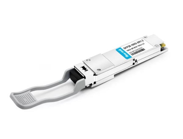
 QSFP28-100G-SR1.2 Single Rate 100G QSFP28 BIDI 850nm & 900nm 100m LC MMF DDM Optical Transceiver
$280.00
QSFP28-100G-SR1.2 Single Rate 100G QSFP28 BIDI 850nm & 900nm 100m LC MMF DDM Optical Transceiver
$280.00
-
 QSFP28-100G-BDRX 100G QSFP28 BIDI 850nm & 900nm Only Receiver 100m LC MMF Optical Transceiver
$379.00
QSFP28-100G-BDRX 100G QSFP28 BIDI 850nm & 900nm Only Receiver 100m LC MMF Optical Transceiver
$379.00
-
 QSFP28-100G-SRBD Dual Rate 40G/100G QSFP28 BIDI 850nm & 900nm 100m LC MMF DDM Optical Transceiver
$449.00
QSFP28-100G-SRBD Dual Rate 40G/100G QSFP28 BIDI 850nm & 900nm 100m LC MMF DDM Optical Transceiver
$449.00
-
 Q28-100G32-BX10 100G QSFP28 BIDI TX1331nm/RX1271nm PAM4 Single Lambda LC SMF 10km DDM Optical Transceiver Module
$500.00
Q28-100G32-BX10 100G QSFP28 BIDI TX1331nm/RX1271nm PAM4 Single Lambda LC SMF 10km DDM Optical Transceiver Module
$500.00
-
 Q28-100G23-BX10 100G QSFP28 BIDI TX1271nm/RX1331nm PAM4 Single Lambda LC SMF 10km DDM Optical Transceiver Module
$500.00
Q28-100G23-BX10 100G QSFP28 BIDI TX1271nm/RX1331nm PAM4 Single Lambda LC SMF 10km DDM Optical Transceiver Module
$500.00
-
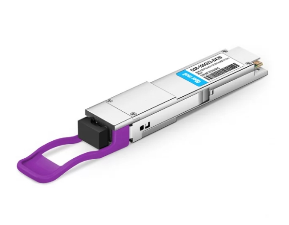
 Q28-100G23-BX20 100G QSFP28 BIDI TX1291nm/RX1311nm Single Lambda LC SMF 20km PAM4 DDM Optical Transceiver Module
$600.00
Q28-100G23-BX20 100G QSFP28 BIDI TX1291nm/RX1311nm Single Lambda LC SMF 20km PAM4 DDM Optical Transceiver Module
$600.00
-
 Q28-100G32-BX20 100G QSFP28 BIDI TX1311nm/RX1291nm Single Lambda LC SMF 20km PAM4 DDM Optical Transceiver Module
$600.00
Q28-100G32-BX20 100G QSFP28 BIDI TX1311nm/RX1291nm Single Lambda LC SMF 20km PAM4 DDM Optical Transceiver Module
$600.00
-
 Q28-100G94-BX30 100G QSFP28 BIDI TX1309nm/RX1304nm Single Lambda LC SMF 30km PAM4 DDM Optical Transceiver Module
$1100.00
Q28-100G94-BX30 100G QSFP28 BIDI TX1309nm/RX1304nm Single Lambda LC SMF 30km PAM4 DDM Optical Transceiver Module
$1100.00
-
 Q28-100G49-BX30 100G QSFP28 BIDI TX1304nm/RX1309nm Single Lambda LC SMF 30km PAM4 DDM Optical Transceiver Module
$1100.00
Q28-100G49-BX30 100G QSFP28 BIDI TX1304nm/RX1309nm Single Lambda LC SMF 30km PAM4 DDM Optical Transceiver Module
$1100.00
-
 Q28-100G49-BX40 100G QSFP28 BIDI TX1304nm/RX1309nm Single Lambda LC SMF 40km PAM4 DDM Optical Transceiver Module
$1200.00
Q28-100G49-BX40 100G QSFP28 BIDI TX1304nm/RX1309nm Single Lambda LC SMF 40km PAM4 DDM Optical Transceiver Module
$1200.00
-
 Q28-100G94-BX40 100G QSFP28 BIDI TX1309nm/RX1304nm Single Lambda LC SMF 40km PAM4 DDM Optical Transceiver Module
$1200.00
Q28-100G94-BX40 100G QSFP28 BIDI TX1309nm/RX1304nm Single Lambda LC SMF 40km PAM4 DDM Optical Transceiver Module
$1200.00
-
 Q28-100G32W-BX20 100G QSFP28 BIDI TX1310nm/RX1280nm LWDM4 Simplex LC SMF 20km with RS FEC DDM Optical Transceiver Module
$1300.00
Q28-100G32W-BX20 100G QSFP28 BIDI TX1310nm/RX1280nm LWDM4 Simplex LC SMF 20km with RS FEC DDM Optical Transceiver Module
$1300.00