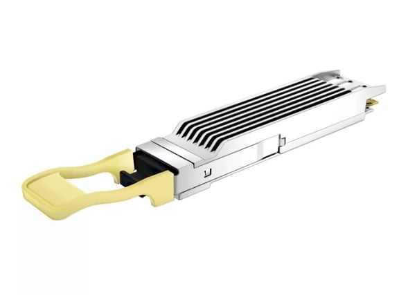
Modern high-speed data communication networks would be incomplete without the OSFP (Octal Small Form-factor Pluggable) 400G DR4 optical transceiver module. It is made to address the increasing bandwidth requirement for data center and telecommunication setups; this module comfortably allows the transportation of data traffic of as much as 400 Gbps on a multimode optical fiber. Each of the modules has a laser design, in which the signal is steered through long distances efficiently without compromising response time or power use. This paper discusses the specifications, working mechanisms, and uses of the OSFP 400G DR4 transceiver, helping the reader understand how this technology is evolving and revolutionizing the world of optical networking.
What is an OSFP 400G DR4 Transceiver?
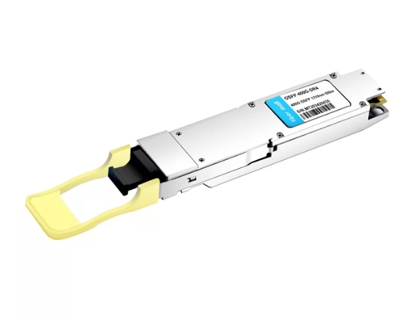
Overview of OSFP 400G Specifications
About 850 nm wavelength is used for the OSFP 400G DR4 transceiver module which is primarily designed to allow transmission through the multimode fiber (MMF) up to 100m. This transceiver module features a 4-channel architecture, which allows sending 100 Gbps each to achieve an aggregated total of 400 Gbps. The module is designed in accordance with IEEE 802.3bs standard for Ethernet over 400m and is also compliant with OIF standards of optical modules. Deemed a low-power device for high-density data center applications, the power consumption of the module ranges around 8 – 10 watts. In addition to that, due to its OSFP form factor, hot-swappable installation and de-installation are greatly facilitated as well.
How DR4 Enables High-Speed Data Transmission?
The DR4 architecture supports a large amount of data transfer by a parallel optical data transfer technique comprising four separate channels. The design further allows data to be transmitted through all the channels at the same time, since each channel can handle data rates of up to 100 Gbps each. In addition to the effective bandwidth increase, this approach more also lessens the latency since the parallel channels are served seamlessly rather than relying on a single channel in a serial manner. In addition, the dependence on multimode fibers with an 850 nm cutoff wave optimizes the signal and prevents dispersion over a short distance so that high and reliable data cannot be affected in modern data centers. The DR4 transceiver is also well designed so as to approach the minimal power that is wasted, hence improving energy efficiency in situations where modern high-speed networking technologies are employed.
Advantages of Using OSFP Transceivers in Data Centers
The use of OSFP transceivers in data centers comes with a number of benefits. The first noteworthy aspect is that a higher density of connectivity is achieved by the use of the OSFP form factor, which means a much higher number of ports can be fitted in the existing network, thereby increasing the packing efficiency. The second benefit is that OSFP partner transceivers are also hot-swappable, and this ensures that maintenance and upgrading do not take the network down, and in return, the downtime is kept at a minimum consolation, and the operation gets more efficient. Furthermore, OSFP transceivers exhibit an extensive array of supported data rates (up to 400 Gbps) as well as support for interoperability with various networking technologies, which enhances their applicability within the industry. Last but not least, the reduced power consumption of OSFP technology aids in the lower operational costs and the lower thermal footprint, which is very key in energy-conserving data center operations. All these advantages, therefore, make OSFP transceivers a practical solution for the needs of today’s data centers.
How Does OSFP PAM4 Technology Work?
Basics of PAM4 1310nm Signaling
PAM4 (Pulse Amplitude Modulation with 4 levels) is a more advanced technique that increases data transmission capacity by twofold per transmitted symbol. In the case of 1310nm signaling which is common in long-distance optical transmission PAM4 enhances the spectral efficiency by twofold as compared to the simple NRZ signaling scheme.
This modulation scheme achieves this by carrying four levels of amplitudes in the transmitted signals, thus resulting in a higher data rate at no additional bandwidth expansion. At the wavelength of 1310nm where singlemode fibers are primarily used for long-distance communication up to about 10 kilometers common specifications have proven effective due to low signal loss in the fibers.
What PAM4 1310nm signaling does is enhance performance and reliability by utilizing high-level error correction and adaptive equalization to conceal the effects of the channel. In addition to the enhancement in efficiency, PAM4 also proves to be very imperative in improving signal integrity, which is a necessity for the surging requirements of high-speed data application in modern-day data centers. Amounts of the order of 200 Gbps or more are reported as data rates achievable using PAM4, which also very efficiently and almost unconditionally elevates the throughput parameters of crowded network fiber infrastructures.
Why PAM4 1310nm is Crucial for 400G Ethernet?
For 400G Ethernet technology, PAM4 1310nm signaling is crucial as it allows for range efficiency that enhances data transmission performance without compromising range. As the need for network connectivity increases, there comes a need for larger bandwidth. With PAM4, it is possible to have 400G Ethernet working on an effective data rate of 400 Gbps as this technology allows the modulation of two bits per symbol using four levels of amplitude instead which is necessary in order to deal with the rapid increase of data volumes. Equally important, the 1310nm wavelength provides a compromise between the operational range and performance, thus allowing 10km long single-mode fiber transmission with minimal loss in efficiency. This feature is essential for the efficient implementation of broadband network interconnections and spine links between data centers, enabling networks to accommodate increased data traffic resulting from cloud and large file transfers, among other modern uses. Thus, the application of PAM4 1310nm on 400G Ethernet systems becomes a good means of addressing the next generation of networks while at the same time making use of the facilities present.
Exploring Top PAM4 1310nm and FEC Solutions
In the effort to realize good PAM4 1310nm alternatives for 400G Ethernet, a number of the businesses have surfaced that apply sophisticated technologies, in which FEC has been included, to ensure that data can be transmitted correctly.
- Cisco Systems: Cisco expresses their desire for the PAM4 technology by the inclusion of this technology in their optical networking product portfolio in their Constitution. Forward error correction (FEC) is employed in their solutions to enhance the error correction capabilities, which affords them good performance in bad environments. The emphasis of the study is to build efficient and high-capacity data center interconnects, which are a response to the increasing appetite for bandwidth.
- Broadcom: A number of PAM4-phased transceivers for transmission distances and signal integrity have come forth in Broadcom’s range of products enriched with the mentioned features. The performance of such products is often beyond reasonable point as they are integrated into basic architectures which are in place for networks and they somehow aid in bringing savings in high speed data systems.
- Marvell Technology Group: In the case of other players such as Marvell, a complete PAM4 1310nm solution with the effect of FEC on its implementation is offered also in an attempt to hinder signal loss and improve network function. Other remarkable aspects of their advanced solutions address the vacuum created by high density locations within the data centers so that the performance metrics are not compromised as the traffic growth is acted upon.
The significant involvement of these companies highlights the relevance of PAM4 and FEC in emerging high-speed Ethernet networks, making data transfer faster and more reliable for various applications.
What are the Connection Standards for OSFP-400G-DR4?
Compatibility with QSFP-DD and Other Form Factors
The OSFP-400G-DR4 is designed to be backwards compatible with existing form factors, such as the QSFP-DD, so it can plug into systems already in use. Thus, this compatibility increases the versatility of network design, allowing for many interconnections and configurations in the data center. Furthermore, OSFP-400G-DR4 has an ultra-compact and high-density structure, which optimizes the area and works efficiently in high-capacity applications.
Using OSFP Transceivers with SMF and MMF
There are two ways of attaching the Optical Multi-Channel Transmission Interface Plug Optical Fiber (OSFP) transceivers, and they provide flexibility of use in different places. While this is applicable when using SMF, OSFP transceivers can extend transmission distances and are applicable in communication links such as those in metropolitan area networks (MANs) and long-distance data center interconnects where it is ordinarily difficult to imagine media. However, in the case of MMF, OSFP transceivers offer broadband access but at short distances, which are suitable for data in-building networks and short-reach applications. What is more, the dual nature of OSFP transceivers not only enhances scalability but also gives network designers the opportunity to customize the fiber structure for particular tasks without compromising the functionality of the network.
Importance of RoHS Compliance
RoHS (Restriction of Hazardous Substances), that is most followed in the manufacturing of electronic equipment and whose purpose is to ensure that the product does not contain specified hazardous materials such as lead, mercury, etc above the allowable limits or permissible level. This is necessary in promoting progressive environmental conservation and health protection through minimization of the dumping of toxic waste in dump sites and proper recycling of materials. In addition, the consumer electronic design policy is starting to be advocated by many authorities and organizations across the globe, including the European Union. The promotion of these standards not only instills a culture of concern for the environment but also improves competitiveness in the market, where similar products are turning out to have great concern imposed on electronic products by consumers and companies. Similarly, by ensuring that the materials used are compliant with RoHS, the end-product quality and reliability can also be enhanced as the manufacturers engage in more responsible material selection and manufacturing processes.
How to Choose the Right 400G OSFP DR4 Module?
Factors to Consider for Single Mode and Multimode Fibers
In choosing between single mode and multimode fibers for connecting 400G OSFP DR4 modules the following need to be noted:
- Distance Constraints: Unidirectional single-mode fiber is best suited when the cable either acts as a backbone or stretches over a large distance. On the contrary, multi-mode fiber technology has proven useful in a limited geographical range.
- Bandwidth Specification: In comparison to multilayer fibers with bandwidth restrictions on the distance, single mode fibers have a higher bandwidth thus can be utilized in applications which require high data transmission.
- Financial Implications: Single mode fibers are more costly due to the cost of installation and shrinkage of light whereas multimode fibers are inexpensive and do not require a lot of effort to set up.
- Design Architecture: Other works may actually dictate the type of fiber to use; it is important to check for the existing systems to achieve Shannon’s limit.
- Conditions of Use: Unlike the Multimode type that has specific areas of application, the single Mode type has relatively better performance under various environmental hazards but has the location of application limiting its extent of deployment.
Comparing OEM and Compatible 400GBASE-DR4
With 400GBASE-DR4 modules, OEM modules need to be benchmarked against compatible options for their evaluation in terms of performance, reliability, and cost. Below is an exhaustive analysis based on critical parameters:
Performance Capabilities:
- OEM Modules: Usually, such models strictly comply with the requirements of the manufacturer’s rules and all relevant standards (IEEE 802.3bs) members’ governments, thus they come with the pledge that they meet all standards. They generally are better thermally and in error rates giving good conditions for data transport for long time durations.
- Compatible Modules: There are many compatible modules that are commercially available that satisfy first order requirements and performance specifications but do not adhere consistently to the specifications in sounds maintenance practices. Such variance tends to happen especially in conditions where networks are under stress.
Cost:
- OEM Modules: These products are typically more expensive since they are branded and come with the warranty provisions and hence this is branded as a costly feature. The higher cost is necessary due to the comparatively low failure rates and assistance that is provided.
- Compatible Modules: These are often a more viable option as they are usually 30-50% cheaper compared to the options provided by manufacturers. However, additional expenditures should be taken into account, such as higher risk of failure rates or troubles with compatibility.
Warranty and Support:
- OEM Modules: A manufacturer usually offers a good warranty plan which, in most cases is several years long and is often accompanied with a particular technical assistance on behalf of the manufacturer.
- Compatible Modules: There is a great variation in the terms of warranties and some may even provide very limited or no customer assistance at all. It is important to evaluate the particular terms and conditions of the compatible modules especially.
Compatibility:
- OEM Modules: OEM modules are thoroughly tested and developed to ensure compatibility with other devices using that framework, specifically designed to work with that particular brand switches and routers.
- Compatible Modules: Many such modules are made to work with reputable brands; however, in some cases, they may not work so well within the operational range of the infrastructure. In this case, doing the testing is advisable.
Market Reliability:
- OEM Modules: As the first party products, they usually enjoy strict quality assurance and steady performance in the market becoming thus a guarantee for use in the times to come.
- Compatible Modules: As for the markets of such compatible modules, it is very much a mixed bag where there is reliance on other companies and thus variation of quality and functionality is found. End-users must perform proper due diligence in identifying authentic manufacturers in the industry.
In conclusion, the issue of whether to use an OEM 400GBASE-DR4 module or a compatible 400GBASE-DR4 module boils down to what is important, the cost or the reliability and performance. Learning about the distinction outlined above will assist businesses in the procurement of goods that meet their exact network requirements.
Cost Implications of Different Optics
In deliberating the problem of pricing for different optical transceiver module options, such as OEM and compatible options, one needs to take into consideration both the direct and indirect costs involved.
- Pricing Schemes: Modular or OEM optics, by their sheer nature of being manufactured in-house, come at an extra cost. This upfront cost is usually worth it because it buys ‘peace of mind’ in the future in terms of performance and integration into existing networks to avoid downtimes. On the other hand, these compatible modules usually have a low initial cost, which appeals very well to low-income consumers. Nonetheless, such savings can be a result of inadequate/poor performance and reliability, which lead to higher maintenance costs.
- Total Cost of Ownership (TCO): Aside from the price of the equipment itself, firms should factor in what they call the total cost of ownership; this covers the costs of installation, maintenance, and operation. Such an initial cost on the compatible equipment may be attractive; however, there might be a hidden cost somewhere such that the total cost of ownership becomes higher if there are more breakdowns and repairs or replacements compared to the OEM products.
- Long-Term Value: The value gained through purchasing OEM modules may be much better in the long run in terms of adherence to standards, compliance, and additional support. This is especially true for companies whose normal operations would be interrupted by a faulty module that could otherwise have been eliminated by having instead purchased a module that one would classify as a spare.
To sum up, although compatible optics can present a cost-saving option, it is important to analyze the benefits versus the performance impact and reliability over time. Businesses should evaluate such factors against their own networking needs and financial situation.
What are the Installation and Maintenance Best Practices?
Setting Up OSFP Modules in Data Center Switches
- Compatibility Check: Confirm the appropriateness of the OSFP module with the data center switch model to achieve the intended purpose.
- Power Down the Switch: This is the most critical step. One should switch off the power supply to the module before it is installed. This is to avoid electrical interference.
- Insertion: The OSFP module’s mounting is executed by pushing further the module into the port ensuring that it clicks, with no undue pressure applied.
- Power Up The Switch: Once the installation procedure has been completed, restore power to the switch system and observe the proceeding steps that the operating system initiates that would indicate presence of the module.
- Configuration: Go to the interface of management of the switch and configure settings of the inserted OSFP module according to the needs of the network.
- Testing: Carry out tests on connectivity which aims at determining whether the integration of the OSFP module into the network was successful.
- Regular Monitoring: Set range of intervals to check the performance statistics of the OSFP module in order to make interventions before the problem arises.
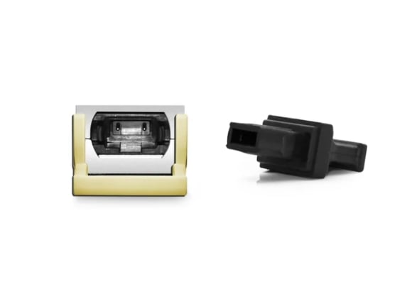
Guidelines for Fiber Patch Cables and Adapters
- Cable Type Selection: Appropriate fiber optic cable chooses either single mode or multi-mode cable depending on the distance as well as the rate of the required network data. Single-mode is preferred in long-distance communication while multi-mode is used in short distances.
- Connector Compatibility: Find out whether the fiber patch cable connectors will be able to fit into the devices and equipment being used (for example, LC, SC, ST). The connectors did not match, which may have prevented connectivity from happening.
- Cable Length: Based on the available slack on the cables, choose the length of the patch cables so that they will be able to reach the ports where they will be plugged without putting unnecessary strain on the ports. Longer cables are able to cause a loss of signal.
- Quality and Standards: Choose high quality and standard cables and adapters complying with ISO/IEC standards to be able to use the copper cables for long periods. This is especially crucial in areas with a lot of data traffic.
- Proper Handling: Fiber cables must not be tangled or bend nor have kinks These will overall reduce the quality of the signal. Poor repairs which may cause disorganization and injury must be taken from the wire cables.
- Regular Inspection: Communication should be possible through fiber patch cables and fiber cable connectors adapter on a reasonable time come due along with all devices wherever for misuse. Look for signs of physical damage and replace any components that are by-physical nature and bring a functional deficit to the working environment.
- Test & Certification: Conduct the internal testing of the faculties of the installed fiber optics cables, such as measuring loss or, checking connectivity. This assists towards early detection of any complications and guarantees reliability in the network infrastructure.
Maintaining Active Optical Cables and DAC Breakout Cables
Active optical cables (AOCs) and direct attach copper (DAC) breakout cables will require some form of maintenance in order to prolong their lifespans and improve their performance.
- Storage Requirements: Cables should be kept in a cool and dry place as excessive moisture or heat can be harm AOCs. Cables should be kept away from direct sunlight and dampness to prevent corrosion.
- Maintenance: Look for evidence of wear on AOCs and DAC cables and their connectors or the recommended minimum bend radii. Ensure that the plugs are clean from dirt and surrounding dust as organic materials will affect the performance of the cable too.
- Physical / Connections: Pulling or twisting of the cables often at times more than what is required during the installation and or shortening of their installation termination is manadatory. Avoid disconnection of the cables for no apparent reason and if cables has to be label attach them in such a way that their function at both ends is clearly identified.
- Testing or Measurements: Introduce periodic testing to examine the condition of signal flow and other parameters, including the exploitation of errors and delay. Excessive signaling and utilization network diagnostic tools to detect and rectify problems even before they occur is adviced.
- Manufacturer’s Warranty: Use warranties or ask manufacturers for assistance when components fail or need to be recycled. Regular networking maintenance’s that are recommended by the manufacturer should be observed in order not to disturb the network infrastructural up time.
Adopting this type of maintenance will minimize the risk of failure and damage in active optical cables and DAC breakout cables over time.
Future of 400G OSFP DR4 Technology
Upcoming Trends in Optical Interconnect Solutions
- Increased Bandwidth Capacity: Future developments will aim to raise the bandwidth potential to more than 400G due to the increasing volumes of data, especially in the areas of data centers and in cloud computing.
- Integration of AI and Machine Learning: Management of the network and its constituent components, as well as predictive maintenance, will be performed using these technologies, increasing performance and minimizing idle time.
- Enhanced Energy Efficiency: Enhancement of optical interconnect solutions will be based on minimizing energy consumption and help to achieve energy efficiency targets as well as high performance.
- Miniaturization of Components: Progress in materials and engineering will result in smaller and lighter optical connectors and transceivers which will increase the facility utilization of the data centers.
- Adoption of Co-Packaged Optics: This method will allow the installation of optical chips into the electronic components of the device which will minimize delay and power loss and maximize performance.
- Focus on Open Standards: There has been a movement towards the use of more open standards based optical interconnect systems whereby the various systems and equipment will be used together efficiently promoting development whilst lowering costs.
The Potential Move Toward 800G OSFP Modules
The adoption of 800G OSFP (Octal Small Form-factor Pluggable) modules signifies an advancement specifically in evolution with customer trends for higher bandwidth and technology in terms of data center facilities. These modules are built to deliver not just an improvement in data transfer speed but also at least double what current 400G solutions offer. This jump is necessary for those applications that deal with tons of information, such as artificial intelligence, high-frequency trading, and cloud services. Likewise, the integration of co-packaged optics enhancement into the OSFP modules is likely to improve overall performance by reducing latency and increasing power efficiency. Even as the industry gears up to use the fourth generation of these modules, there will be a focus on making the new modules backward compatible so that previous investments in older modules are not lost but the shift to 800G is less awkward.
Impact on Data Center Networking and Storage Solutions
The adoption of 800G OSFP modules integrates greater bandwidth and lower latency, which will greatly transform the data center networking and storage technology. Given that data centers are increasingly faced with the need for stronger solutions due to the explosive growth in data traffic, the 800G technology comes with the architecture required to support real-time analytics and high-performance computing, among other demanding applications. In addition to that, their deployment will also lead to better load balancing and resource utilization, which will improve data management efficiency. Data center operators will also find these hybrid 800G network architectures easier to implement, allowing them to grow the network without having to employ complicated architectures in the first place. Furthermore, the energy efficiency benefits associated with 800G OSFP modules will enhance not just performance but also cut operational costs caused by power requirements and cooling needs.
Reference Sources
Frequently Asked Questions (FAQs)
Q: What is an OSFP 400G DR4 Optical Transceiver Module?
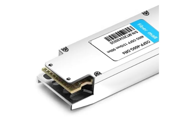
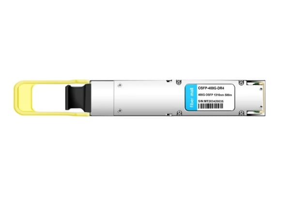
A: Basically, the OSFP 400G DR4 Optical Transceiver Module is yet another advanced Optical Transceiver for Different Area Network (DAN) tasks. It is tailored to the DR4 standard and goes up to 400Gbps. This transceiver adopts PAM4 encoding scheme and works in 1310nm over a distance of 500m attachment.
Q: What is the operating range of the 400G DR4 OSFP module?
A: The 400G DR4 OSFP module can transmit and receive data via single-mode fiber (SMF) cables with a maximum distance of up to 500m.
Q: What does PAM4 mean in the context of an OSFP transceiver?
A: Thus, PAM4 or Pulse Amplitude Modulation 4 is a modulation scheme that consists of modulating four (4) levels, which enhances the behavior of functional transmission of data. In the case of an OSFP transceiver, this technology directly allows for the 400Gbps data rate via 2 bits per symbol in one transmission.
Q: Do the Arista switches work with the OSFP 400G DR4 module?
A: Yes, the OSFP 400G DR4 module works with all Arista switches, but it is meant for the specific model OSFP-400G-DR4.
Q: What is the importance of the 1310nm wavelength in the OSFP transceiver?
A: This photo of the EDFA international convention shows that the OSFP optical transceiver also transmits at 1310nm for a good reason, as this wavelength is in the window most favorable for loss and dispersion in single-mode fibers (SMF).
Q: What constitutes the DR4 OSFP PAM4 Silicon Photonics transceiver’s capability?
A: Important elements of the DR4 OSFP PAM4 Silicon Photonics transceiver include 400Gbs throughput performance, the PAM4 technology modulation, having a 1310nm optical wavelength and potentially covering 500m. Moreover, it is scalable into higher density data center and meets the requirement of OSFP MSA.
Q: What applications are applicable for the 400G OSFP DR4 Flat Top module?
A: The 400G OSFP DR4 Flat Top module can be used in very high speed data center interconnects, within high performance computing environment, and in the advanced optics storage networking….It is rating for 400 Gigabit Ethernet services.
Q: What are the variations between QSFP28 and OSFP in their works?
A: Though a few branches of QSFP28 modules that support single channel connections solely at bandwidths of hundred gigabits ethernet or forty gigabits ethernets could be used. Some function at higher frequencies,400Gbps, which renders them more functional than SOSP interfaces or even limited QSFP28 section converters. One foremost difference is the fact that the OSFP could also allow for more advanced modulation schemes PAM4, as mentioned above.
Q: What is the purpose of FEC in an SMF FEC Optical Transceiver Module?
A: In an SMF FEC Optical Transceiver Module, FEC (Forward Error Correction) aids in error checking and correction during data transfer thus increasing efficiency in communication and data loss through the optical fiber medium.
Q: Can the 400GBASE-DR4 OSFP PAM4 1310nm module be operated on wireless and 5G optical networks?
A: Yes, it is possible to operate the 400GBASE-DR4 OSFP PAM4 1310nm module on wireless and 5G optical networks. It has provisions for high data rate transmissions and therefore meets the fast rising data requirements for 5G networks.
Related Products:
-
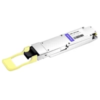
 OSFP-400G-DR4 400G OSFP DR4 PAM4 1310nm MTP/MPO-12 500m SMF FEC Optical Transceiver Module
$800.00
OSFP-400G-DR4 400G OSFP DR4 PAM4 1310nm MTP/MPO-12 500m SMF FEC Optical Transceiver Module
$800.00
-
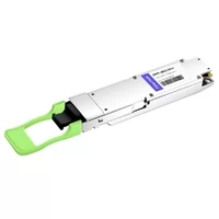
Arista Networks OSFP-400G-DR4 Compatible 400G OSFP DR4 PAM4 1310nm MTP/MPO-12 500m SMF FEC Optical Transceiver Module
$800.00
-
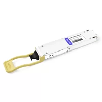
Edgecore Compatible 400G OSFP DR4 PAM4 1310nm MTP/MPO-12 500m SMF FEC Optical Transceiver Module
$800.00
-
OSFP-400G-DR4+ 400G OSFP DR4+ 1310nm MPO-12 2km SMF Optical Transceiver Module
$850.00
-
Arista OSFP-400G-XDR4 Compatible 400G OSFP DR4+ 1310nm MPO-12 2km SMF Optical Transceiver Module
$850.00
-
OSFP-400G-DR4-FLT 400G OSFP DR4 Flat Top PAM4 1310nm MTP/MPO-12 500m SMF FEC Optical Transceiver Module
$700.00