The NVIDIA HGX B200 is NVIDIA’s latest high-performance computing platform, based on the Blackwell GPU architecture. It integrates several advanced technologies and components designed to deliver exceptional computing performance and energy efficiency.
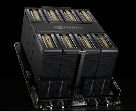
The complete system height with the HGX B200 air-cooled module reaches 10U, with the HGX B200 air-cooled module itself accounting for approximately 6U.
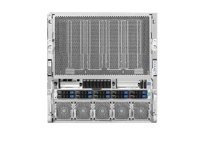
Exxact TensorEX 10U HGX B200 Server
6x 5250W Redundant (3 + 3) power supplies
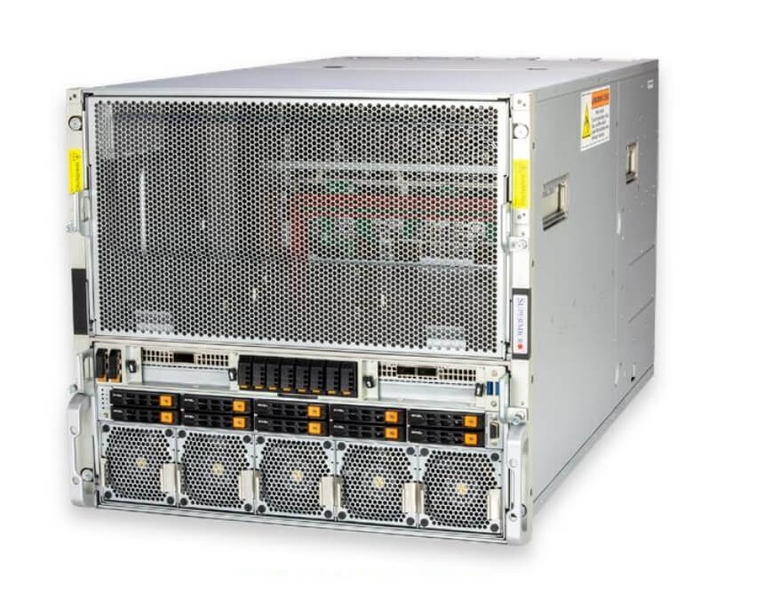
SuperServer SYS-A22GA-NBRT(10U)6x 5250W Redundant (3 + 3) power supplies
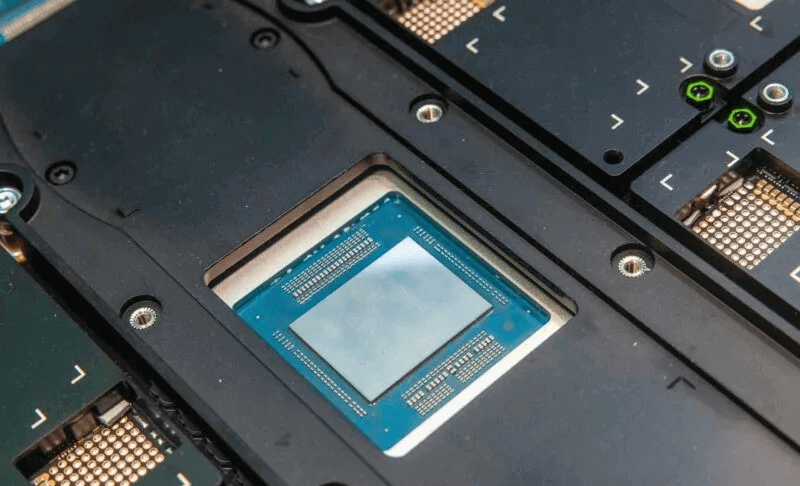
At the OCP Global Summit 2024, several new photographs of the NVIDIA HGX B200 were showcased. Compared to the NVIDIA HGX A100/H100/H200, a significant change is the relocation of the NVLink Switch chip to the center of the component, rather than at one side. This change minimizes the maximum link distance between the GPUs and the NVLink Switch chip. The NVLink Switch now consists of only two chips, compared to four in the previous generation, and their size has notably increased.
Near the edge connectors, a PCIe Retimer has replaced the NVSwitch. These Retimers typically use smaller heatsinks as their TDP (Thermal Design Power) is around 10-15W.
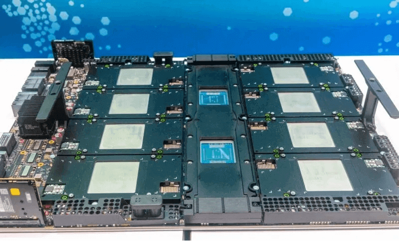
HGX B200 Motherboard Without Heatsinks – 1
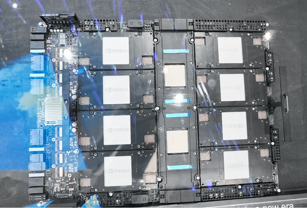
HGX B200 Motherboard Without Heatsinks – 2
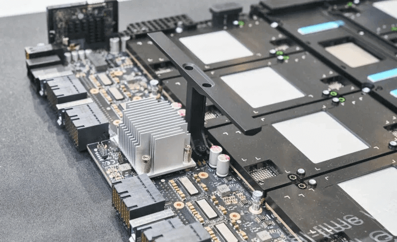
HGX B200 Motherboard Retimer Chip Heatsink
The silkscreen on the top surface of the EXAMAX connector indicates that this is an Umbriel GB200 SXM6 8 GPU baseboard, with the part number: 675-26287-00A0-TS53. Close inspection reveals that the Retimer chip manufacturer is Astera Labs.
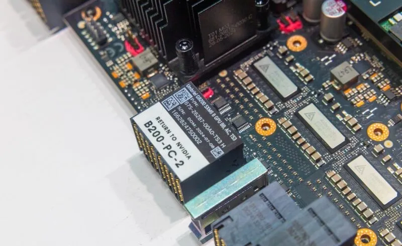
NVIDIA HGX B200 Part Number Information
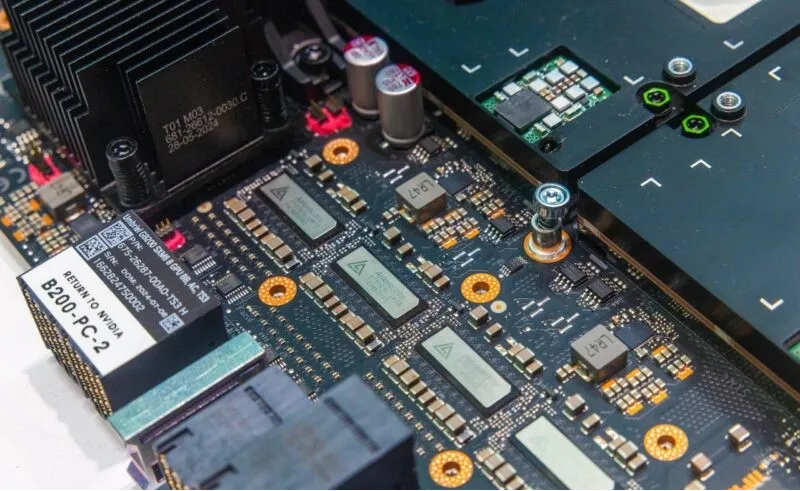
NVIDIA HGX B200 Astera Labs Retimer Chip Close-Up
The perimeter of the HGX B200 motherboard is encased in a black aluminum alloy mounting frame used to secure heatsinks and attach thermal materials.
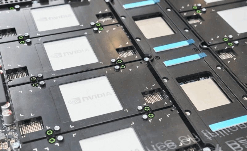
NVIDIA HGX B200 Motherboard Heatsink Mounting Frame
Below are images of the NVLink Switch chip showcased at the 2024 OCP Global Summit.
Considerations for the Liquid Cooling Solution for HGX B200
NVIDIA has established two TDP (Thermal Design Power) values for the B200: 1200W for liquid cooling and 1000W for air cooling. Additionally, the B100 offers a 700W range similar to the previous H100 SXM, allowing OEM manufacturers to reuse the 700W air cooling design. Higher TDP limits correlate with increased clock frequencies and the number of enabled arithmetic units, thereby enhancing performance. In fact, FP4 (Tensor Core) performance for the B200/1200W is 20 PFLOPS, for the B200/1000W is 18 PFLOPS, and for the B100/700W is 14 PFLOPS.
The OAI system employs a 4×2 cold plate (i.e., water pipe) loop, with cold liquid initially flowing into the cold plates over OAM 1-4, absorbing heat and then warming up slightly before passing through the cold plates over OAM 5-8. This resembles air cooling, where airflow sequentially passes through the heatsinks of two CPUs.
In contrast, an 8×1 cold plate loop layout distributes cold liquid evenly to all 8 OAMs, avoiding higher temperatures in half of the OAMs but potentially incurring higher costs due to additional piping.
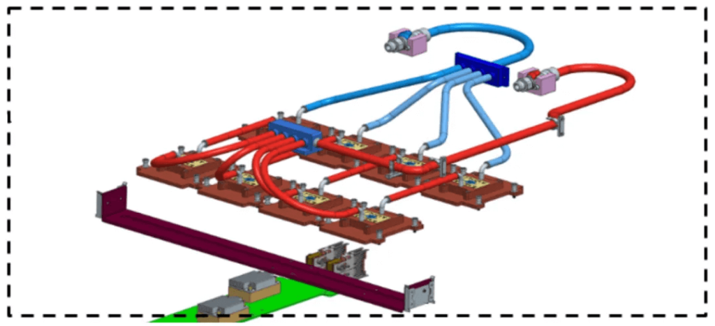
In the OAM 1.5 specification, the cold plate assembly is illustrated in a 4-parallel-2-series arrangement.
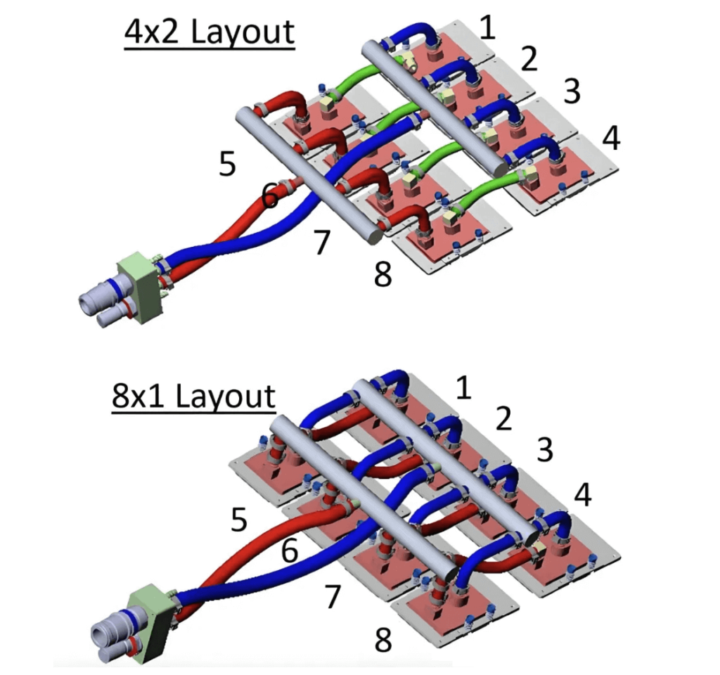
4-parallel-2-series versus 8×1 Configuration
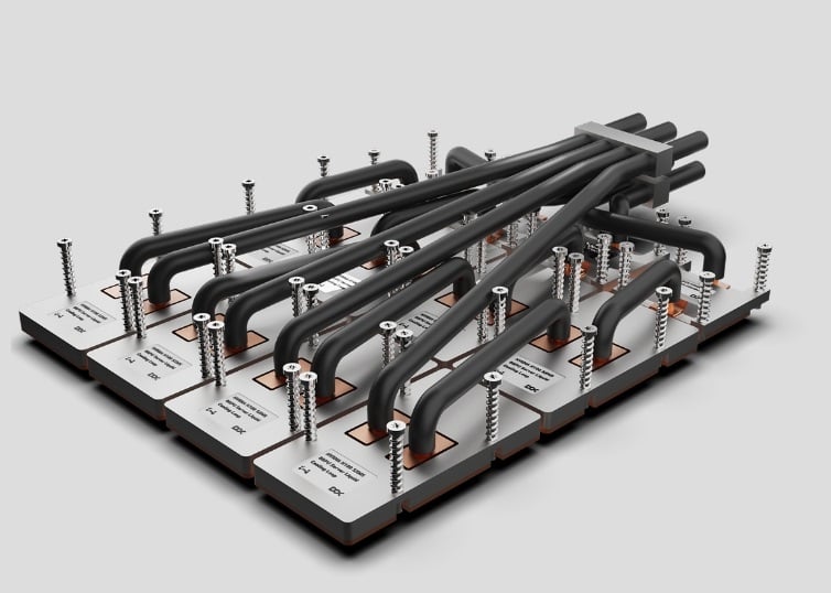
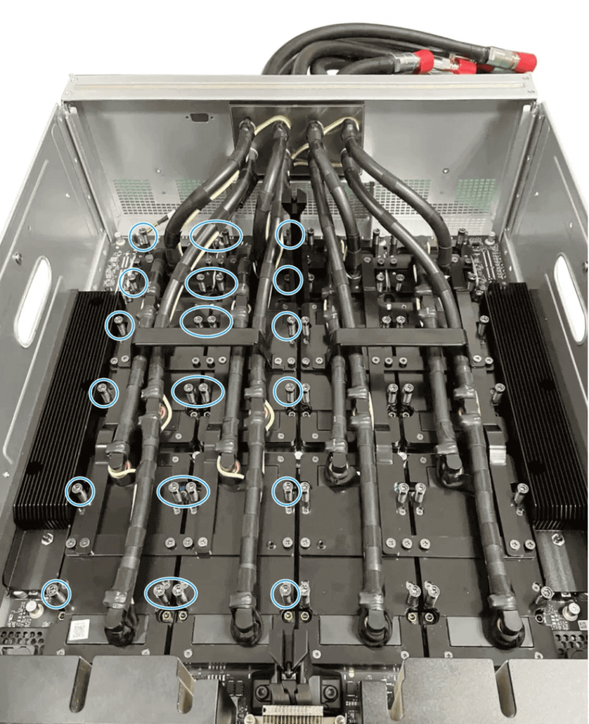
H3C R5500 G6 H100 Module Liquid Cooling 4-parallel-3-series (2 GPUs in Parallel + 1 Switch in Series)
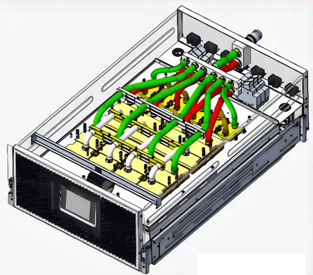
Based on the above H100 cold plate configurations, the considerations for the B200 liquid cooling solution are as follows: The 8 GPUs and 2 Switches are divided into 2 groups. Each group consists of 4 GPUs and 1 Switch. Both groups use the same liquid cooling scheme. Each group has 2 inlet and 2 outlet ports for the cold plates. The top 2 GPUs are in parallel and connected in series with the Switch, and the bottom 2 GPUs are also in parallel and connected in series with the same Switch, resulting in 4 inlet/outlet ports on the Switch cold plate.
Alternatively, the manifold can be designed with 6 inlets and 6 outlets, where 4 of the inlets and outlets are used for the 8 GPUs (4-parallel-2-series configuration), and the other 2 inlets and 2 outlets are for the 2 Switches, each connected to the manifold. This approach requires careful consideration of the routing path and space constraints for the piping. However, regardless of the chosen solution, detailed simulation evaluation and practical system design are necessary.
Related Products:
-
 OSFP-800G-FR4 800G OSFP FR4 (200G per line) PAM4 CWDM Duplex LC 2km SMF Optical Transceiver Module
$3500.00
-
 OSFP-800G-2FR2L 800G OSFP 2FR2 (200G per line) PAM4 1291/1311nm 2km DOM Duplex LC SMF Optical Transceiver Module
$3000.00
-
 OSFP-800G-2FR2 800G OSFP 2FR2 (200G per line) PAM4 1291/1311nm 2km DOM Dual CS SMF Optical Transceiver Module
$3000.00
-
 OSFP-800G-DR4 800G OSFP DR4 (200G per line) PAM4 1311nm MPO-12 500m SMF DDM Optical Transceiver Module
$3000.00
-
 NVIDIA MMS4X00-NM-FLT Compatible 800G Twin-port OSFP 2x400G Flat Top PAM4 1310nm 500m DOM Dual MTP/MPO-12 SMF Optical Transceiver Module
$1199.00
-
 NVIDIA MMA4Z00-NS-FLT Compatible 800Gb/s Twin-port OSFP 2x400G SR8 PAM4 850nm 100m DOM Dual MPO-12 MMF Optical Transceiver Module
$650.00
-
 NVIDIA MMS4X00-NM Compatible 800Gb/s Twin-port OSFP 2x400G PAM4 1310nm 500m DOM Dual MTP/MPO-12 SMF Optical Transceiver Module
$900.00
-
 NVIDIA MMA4Z00-NS Compatible 800Gb/s Twin-port OSFP 2x400G SR8 PAM4 850nm 100m DOM Dual MPO-12 MMF Optical Transceiver Module
$650.00
-
 NVIDIA MMS1Z00-NS400 Compatible 400G NDR QSFP112 DR4 PAM4 1310nm 500m MPO-12 with FEC Optical Transceiver Module
$700.00
-
 NVIDIA MMS4X00-NS400 Compatible 400G OSFP DR4 Flat Top PAM4 1310nm MTP/MPO-12 500m SMF FEC Optical Transceiver Module
$700.00
-
 NVIDIA MMA1Z00-NS400 Compatible 400G QSFP112 VR4 PAM4 850nm 50m MTP/MPO-12 OM4 FEC Optical Transceiver Module
$550.00
-
 NVIDIA MMA4Z00-NS400 Compatible 400G OSFP SR4 Flat Top PAM4 850nm 30m on OM3/50m on OM4 MTP/MPO-12 Multimode FEC Optical Transceiver Module
$550.00
-
 NVIDIA MMS4X50-NM Compatible OSFP 2x400G FR4 PAM4 1310nm 2km DOM Dual Duplex LC SMF Optical Transceiver Module
$1200.00
-
 OSFP-XD-1.6T-4FR2 1.6T OSFP-XD 4xFR2 PAM4 1291/1311nm 2km SN SMF Optical Transceiver Module
$15000.00
-
 OSFP-XD-1.6T-2FR4 1.6T OSFP-XD 2xFR4 PAM4 2x CWDM4 2km Dual Duplex LC SMF Optical Transceiver Module
$20000.00
-
 OSFP-XD-1.6T-DR8 1.6T OSFP-XD DR8 PAM4 1311nm 2km MPO-16 SMF Optical Transceiver Module
$12000.00

