
In the fast-developing telecommunications sector, it is vital to optimize and, in no case, lose fiber optic networks. While using multi-beber push-on (MPO) connectors in rugged, dense applications is increasing, appropriate testing solutions have also become relevant. MPO testers are now essential for the certification, fault detection, and maintenance of fiber optic links. This paper intends to enrich the understanding of MPO testers by detailing their features, advantages, and areas of use. This guide serves as an introduction and a reference, assisting an industry expert in enhancing his/her comprehension of the issues or a technician in applying ways to strengthen work using the MPO testers in fluctuating fiber optic surroundings.
What is an MPO tester, and Why is it Important?
Understanding mpo and 12 fiber Technologies
MPO (Multi-Fiber Push-On) Connectors are very efficient because they require strands of optical fibers in a single connector. In detail, the 12-fiber MPO connector is the most popular, which unites 12 individual fibers in a more compact form. Grouping of fibers results in broader bandwidth and faster data transmission; therefore, these connectors are essential in today’s data centers, telecommunication systems, and high-speed networking systems. Consequently, it is essential to comprehend the basis and usage of MPO and 12-fiber because they greatly help address network architecture issues, speed up the installation process, and preserve a capacity corresponding to increasing amounts of data.
Key Features of an MPO Tester
MPO testers offer several state-of-the-art features that position them as one of the most essential tools that are used in fiber optic testing and maintenance:
- High Accuracy & Speed: These Instruments can take measurements and give diagnostic results very quickly, which is critical to optimizing the performance of dense fiber networks.
- Multi-Fiber Testing Capabilities: They can test several fibers lying in an MPO connector in one go, which is faster than using a single fiber testing tool.
- Loss Measurement: Comprehensive capabilities on loss measurement, both insertion loss and return loss, enable the quality of the network to be gauged well.
- Polarity Verification: MPO testers have an automatic polarity verification feature, which ensures incorrect or proper connectivity of the fibers about the network’s design.
- User-Friendly Interface: If the user interface is intuitive and has a screen showing clear, readable information regarding an error or not, there is no doubt that testing shall be easy as it will be oriented toward those who are less skilled.
- Data Storage and Reporting: These testers have additional data storage features that allow the documentation of the test outcomes to be retained for future analysis.
Integrating these features into MPO testers is also necessary to uphold the reliability and performance of today’s fiber optic networks.
The Role of tester in Fiber Optic Networks
Fiber optic networks require proper maintenance and operational excellence, all enabled through the MPO tester’s performance tests. Speed and precision cut across for efficient diagnosis and undertaking of maintenance work. They minimize the time spent assessing the network by performing multifiber testing, where more than one fiber can be tested simultaneously. Detailed tests are achieved thanks to loss measurement assessments, and automatic standards verification mitigates disturbed connections. The operator interfaces are designed so that e even a less experienced or a more experienced technician can use the tools properly. Digital memory devices help record the results of the tests and thus document the work done and conduct its analysis later on. Thus, the MPO testers are critical for enhancing the installation, support, and repair of the current generation of fiber networks.
How to Use an mpo test Kit?
Setting Up the tester
- Initial Preparation: To start the procedure, open the MPO test kit and check if all parts are there. Before beginning testing, check the device’s battery life and charge it if necessary. Ensure the test cords and connectors are clean to eliminate dirt’s influence.
- Power On the Device: Press the power button to turn on the MPO tester with the onboard MPO connector attached and in position. Wait for the device to conclude the initialization.
- Connecting the Cables: Connect the MPO connector to the relevant port at the tester. Ensure a tight connection to prevent signal loss during the test period.
- Select the Test Parameters: Go through the interface, which helps you set the matters concerned with the mode of operation, including the type of fiber and the number and type of tests to be done, e.g., loss and polarity tests.
- Perform Calibration: The first preliminary calibration is necessary to reliably obtain the quantitative information before carrying out the final tests. Pay attention to the instructions provided by the manufacturer for this step.
- Perform the test: Use the proper Start control to begin the program and automatically feed the MPPM with detecting cells so that the multifiber pro power meter scans optimally. The tester will analyze the fiber optic network according to the selected parameters.
- Put in Writing the Test Location: After the tests have been performed, check the test results provided on the screen. Use the data storage section to save the outcomes for future use and documentation.
Completing these steps helps promote the correct and effective use of an MPO test kit and enhances the functionality and reliability of fiber-based networks.
Key Steps for Conducting a Comprehensive MPO Test:
- Preparation and Inspection: Before embarking on a task, preparation is key; in this case, all equipment, including polishing the MPO connectors, should be checked, as well as the cleanliness of all parts. Where there is dirt or any other form of damage, the accuracy of the test is affected dramatically.
- Powering and Connection: Switch on the MPO tester and connect the MPO cables and fan-out cords to test the MPO connections. Ensure that all connections are snugly fitted without exposure to dirt that may affect the transmission.
- Parameter Selection: The parameters to be tested must be provided to configure the test device correctly. In most cases, this comprises the type of fiber needed, how many channels are to be tested, and what exactly is to be done regarding the said test, such as insertion loss or return loss.
- Calibration: An initial meter calibration is conducted to create a base level for comparison. This step establishes that the metering sensor can measure the parameters at the required conditions.
- Executing Tests: The appropriate tests should be carried out by activating the testing procedure on the device. The MPO tester will carry out the procedures designed by the user about the connections to test the optical fibers.
- Analyzing Results: Once all the tests have been performed, the results are evaluated as shown on the device screen. All data is saved on the device’s internal memory or, if necessary, transferred to external devices for storage and analysis.
- Maintenance and Documentation: In due time, regularly maintain your MPO testing tools and record every test conducted. These documents are essential for reference in the future and for identifying any challenges that may arise.
Following these precise steps contributes to more effective and reliable MPO testing processes, which improve the quality and reliability of your fiber optic system.
Interpreting test results from MPO Tests
This type of understanding involves an in-depth examination of the MPO test measurements. Some of the parameters that are generally measured are insertion loss, return loss, and polarity.
- Insertion Loss (IL): This term describes how much of the optical signal gets lost as it transits through a given fiber optic component. The lower the amount of insertion loss, the better. The acceptable insertion loss values will vary depending on the industry and the type of use.
- Return Loss (RL): Return loss assesses the amount of light reflected towards the source from where it is sourced. High return loss values mean there is less signal reflection and an excellent operable system.
- Polarity: This component of the MPO system ensures that the transmit and receive ways are directed correctly to the respective connectors without any misalignment. If the signals are miss-aligned, communication within the network devices may not be effective.
As a result, when analyzing the test results, it is essential to verify that the values of each of the parameters remain within the limits provided for each criterion. Furthermore, documenting such outcomes is an embarrassment for the system operations since it permits identifying and resolving abnormalities during the system’s operations. It also assists in identifying and resolving potential problems even before they occur from any of the networks by regularly reviewing and comparing sample results.
What are the Benefits of Using an mpo fiber tester?
Improved Efficiency in fiber testing
Compared to the processes without the splitter and cleaning rod, using an MPO fiber tester greatly optimizes the efficiency of the work performed in the process of fiber testing. Using such testers allows the testing of multi-fiber cables in a single operation, thereby allowing for a quicker testing period than the conventional single-fiber testers. Also, some MPO fiber testers may come with pass/fail analysis feature on some tests and thus require less human judgment since industrial standards are followed. These testers are also compact and light, thereby making it possible for the testing to take place at the actual location, which forms part of the requirements for any network technician to ensure optimum performance and reliability on modern fiber optic networks.
Accuracy and Reliability with mpo test set
Habits in the same manner. Because of the combination of different parts, the MPO test set allows the construction of manifold cables with measurable, identical results. These devices are designed to address several fibers simultaneously in hand, and therefore, the chance of making an error as in a single fiber addressing mode is lost. The MPO test sets have various additional provisions like automatic measurement procedures so that the operator does not have to remember how to do things correctly and reporting requirements to avoid too much paperwork. These test sets incorporate advanced features that enable easy and prompt troubleshooting, allowing the necessary repairs to be done instantly. Therefore, network technicians are confident in the information they gather, which enforces the ability of the fiber optic networks to operate efficiently as per the design over a prolonged period.
Common Issues in MPO Testing and How to Solve Them
Troubleshooting polarity Issues
Polarity problems during MPO testing may have negative consequences in fiber optic networks where proper polarity is not observed, for example, fiber mapping errors or signal loss. Primarily, these problems result from the reverse connectivity of the transmitter and receiver ends. To resolve the polarity issues, adhere to the following procedures:
- Ensure the Correct Polarity Configuration: Ensure the MPO connectors comply with TIA-568 standards in Method A, B, or C while being fitted in the plugs. Disconnecting this way is one of the leading causes of these issues.
- Use an MPO Polarity Tester: An MPO tester for polarity will instantly detect any cable polarity issues. These devices can also ensure the proper location of various equipment along the cable.
- Check for cross-connects: Inspect any cross-connects during the installation to ensure they achieve the correct optical path and do not create polarity errors.
- Documentation and Labelling: Cable labeling and cable management have been used to avert polarity problems. Cables must be labeled, and documentation must be updated so that connections can be easily found and followed.
- Automated Testing: Employ test sets with automated tonal checks for polarity misalignment. These can instantly identify polarity errors and notify the technologist, thus quicker problem resolution.
Rapidly resolving such issues will assist in retaining the efficiency of the fiber optic network.
Addressing loss test Failures
In fiber optic networks, loss test failures are critical as they lead to sharp declines in quality. To overcome the following setbacks when baseline performance is not achieved, these steps can be followed:
- Check Connectors and Cables: Dirty or broken connectors are a frequent source of loss. Take great precautions to clean all the connectors using proper cleaning methods and examine connectors for any damage.
- Perform OTDR Testing: Optical Time Domain Reflectometry is worth it in any situation since it allows determining loss points in the fiber link. OTDR results are presented with loss measurement, which generally supports loss location analysis of faulty points, splices, or connectors responsible for high loss.
- Re-terminate or Replace Defective Components: When tracing back some connectors and fibers, they may be found to be defective, and in this case, re-terminating or replacing them is necessary. Termination should be effective in achieving low return and insertion loss.
- Fiber Handling Not Properly Done: Fiber losses could also be attributed to improper bending, stretching, routing, and all other unnecessary activities. Proper installation practices should be observed, especially when controlling an excessive bend radius is involved.
- Look for Microbends and Macrobends: These bends likewise cause major signal loss. Look at the fiber routing, making sure there are no turns or pinch points that will cause problems for micro or macro bending and adjusting them as necessary.
- Verify Splice Quality: Poor splicing tends to increase losses. Examine all splices to make sure they have been done properly, and if they haven’t, it is suggested that they be re-spliced to prevent excessive loss.
The absence of moisture in the core region will most probably guarantee the prevention of such loss test failures, further improving the efficiency and integrity of the fiber optic network.
Dealing with faulty MPO connectors
MPO connectors not properly functioning can be a significant liability for the entire network system. Concerning issues with MPO connectors, the following steps should be undertaken:
- Visual Inspection and Cleaning: Start with chronic visual observation using a microscope to investigate the end faces of the connectors for debris, dirt, and damage. A degreaser alone is ineffective in cleaning the connector; therefore, use lint-free wipes together with degreaser or fiber wet wipes.
- Testing and Validation: Assess the connectors’ efficiency using an MPO tester. This assists in detecting problems like high insertion loss or return loss that could be due to poor connections or dirt.
- Re-Polishing or Replacement: In situations where there are no noticeable performance changes after cleaning, the MPO connectors can be re-polished to improve the quality of the end face. Where replacing the polishing film is not practicable, the disturbed MPO connectors should be exchanged for new ones.
- Proper Mating and Demating Practices: Use appropriate procedures for connecting and disconnecting a connector to prevent breakage. Do not apply force while mating connectors without aligning the alignment pins properly to avoid breakage.
If these steps are complied with, faults within the MPO connectors can be effectively minimized, making it possible to protect the fiber optic network.
How Does MPO Testing Differ for Multimode and Singlemode Fibers?
Differences Between Multimode MPO and Singlemode
The distinction between multimode and singlemode MPO fibers becomes crucial during MPO connectivity testing. The core diameter of the multimode fibers is generally larger (typically 50 or 62.5 micrometers) and is used with shorter operating wavelengths (850 nm and 1300 nm) in singlemode; the core diameter is much smaller in the order of about 9 micrometers and is used with longer operating wavelengths at 1310 nm and 1550 nm. Indeed, for multimode MPO testing, attention is paid to maintaining high bandwidth over short distances while avoiding modal. In contrast, singlemode MPO testing focuses on minimizing insertion loss and accurate centering due to the small core for long-distance application usage. To evaluate and detect possible faults in each particular type of fiber, it is unavoidable to alter the testing parameters and the testing tools concerning these fundamental issues.
Special Considerations for 12 fiber MPO Connections
Whenever 12 fiber MPO connections are involved, some parameters must be attended to to maintain good efficiency and reliability. It’s imperative to focus on the following:
- Polarity Management: The signals must take the correct direction if they are to be polarized correctly. This relates to whether the transmit (Tx) and receive (Rx) are oriented using a procedure like Method A, B, or C to correct this crossover.
- Loss Budget Calculation: For 12 fiber MPO connection Homogenizers, loss budget assessment is an important consideration. This entails determining the provided estimates, including connector loss, splice loss, and fiber attenuation within the entire length of the fiber. Kindly note that total insertion loss should, as much as practically possible, remain within the prescribed limits for observation purposes.
- End-face Cleanliness: The cleanliness of the connectors’ end faces is fundamental in regard to signal and/or information loss. Proper maintenance of the connectors is necessary throughout the technical process. Each connector end face should be inspected, and only clean connectors should be mated together.
- Migration Path to Higher Data Rates: Upgrading to higher data rates in the future, such as moving from 10G to 40G or 100G networks, should also be planned. The commissioning of 12 fiber MPO connections, mainly focusing on these higher data rates, may require more capacity in the form of patch panels, cassettes, and cabling designed to cater to the next generation.
Being mindful of these aspects will likely provide customers with optimum performance and expandability for 12-fiber MPO connections in existing and prospective networking scenarios.
What Tools are Included in an MPO Test Kit?
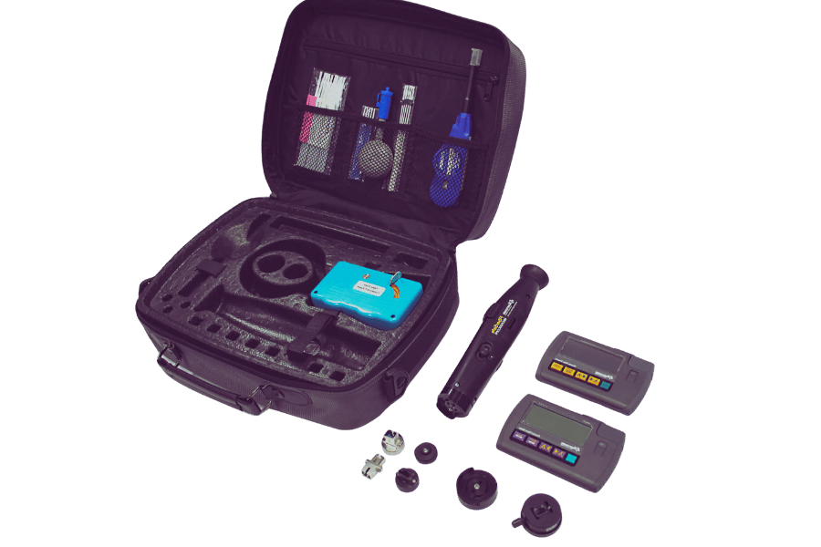
Overview of a Standard test kit
Most of the standard MPO test kits are accompanied by several additional tools needed to test twelve fiber MPO connectors and serve as the base of the kits. Most of the components provided in such kits include:
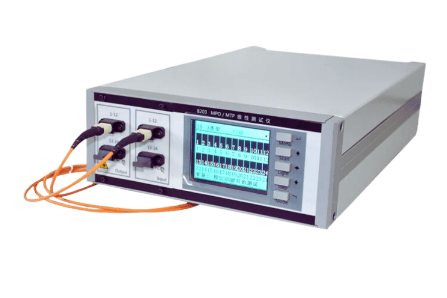
- Optical Power Meter: It records the strength of the optical signal that travels through the MPO connectors to produce necessary evaluative performance metrics of the network.
- Light Source: Working together with the optical power meter, the light source emits a constant light wavelength, usually having a range selected from the following bands: 850nm, 1300nm, 1310nm, and 1550nm for testing both single-mode and multi-mode fiber networks.
- MPO /MTP Test Leads: The test instrument leads connect MPO connectors to the test instruments for testing purposes.
- Inspection Microscope: Used to facilitate the analysis of the end faces of MPO connectors, it helps distinguish foreign bodies, surface scratches, or fractures that may limit the proper transmission of signals.
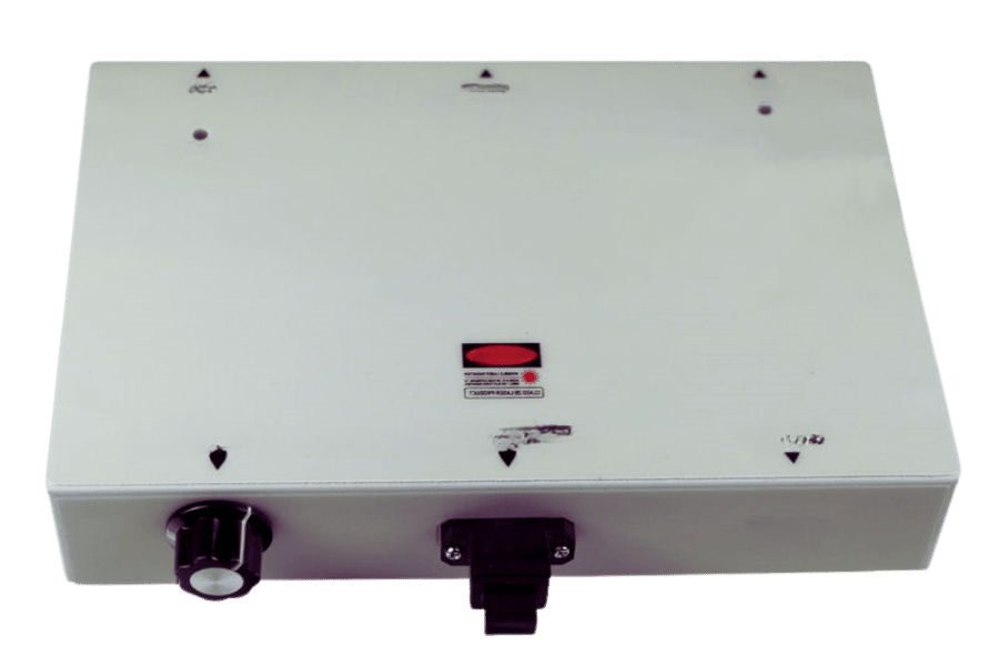
- Visual Fault Locator (VFL): The VFL identifies optical fibers inside the MPO assembly that show increased contrast above the background due to light rays in the form of a bright red laser with reasonable viewing angles.
- Fiber Cleaning Tools: Suitable cleaning devices, such as hydraulic tissues, pads, sticks, or solvents, are provided for the effective cleaning of the end faces of joints to reduce the attenuation of the received optical signals.
For network engineers, an all-inclusive MPO test kit is fundamental for confirming performance, ensuring installation, and maintaining fiber optic network dependency.
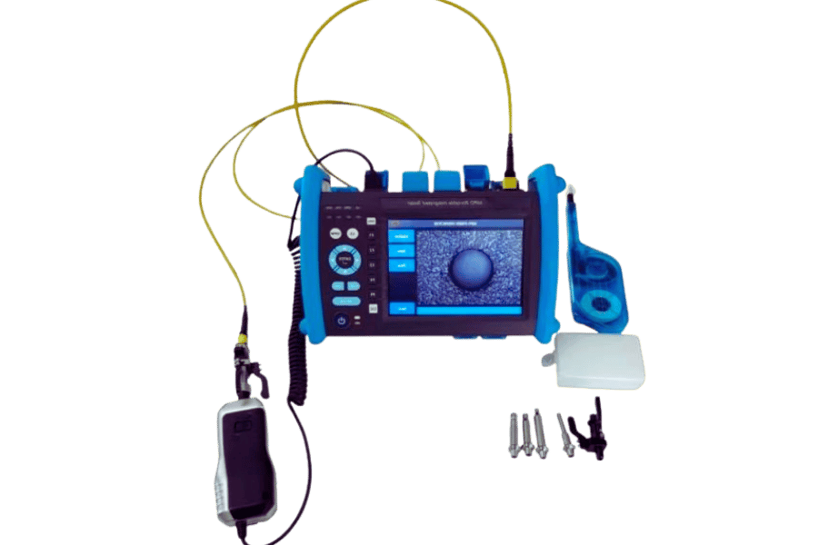
The functionality of the multifiber™ pro-Power Meter
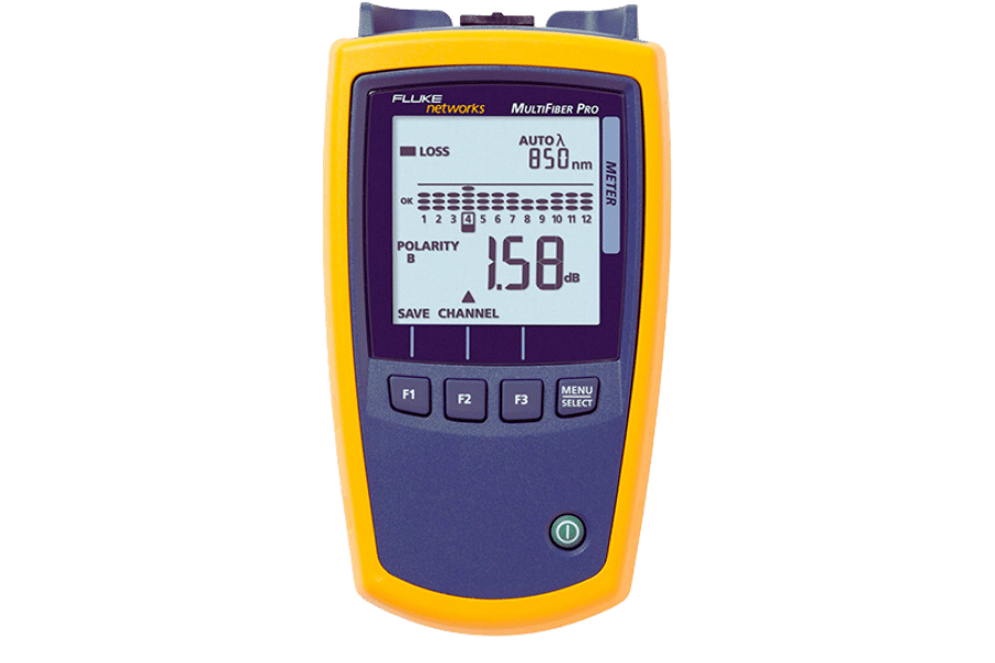
The MultiFiber™ Pro Optical Power Meter has been developed to provide easy and speedy testing of MPO connectors within packed fiber networks. The main features of this product include:
- Simultaneous Testing: This device features a simultaneous measuring capability for the power level in all 12 fibers arranged within the MPO connector interface, thereby reducing the time and labor expended during the testing process.
- Automatic Detection: This device system uses automatic, single-mode, or multimode fiber in imaging. One of them identifies the type of fiber optic network in use so that correct readings are obtained.
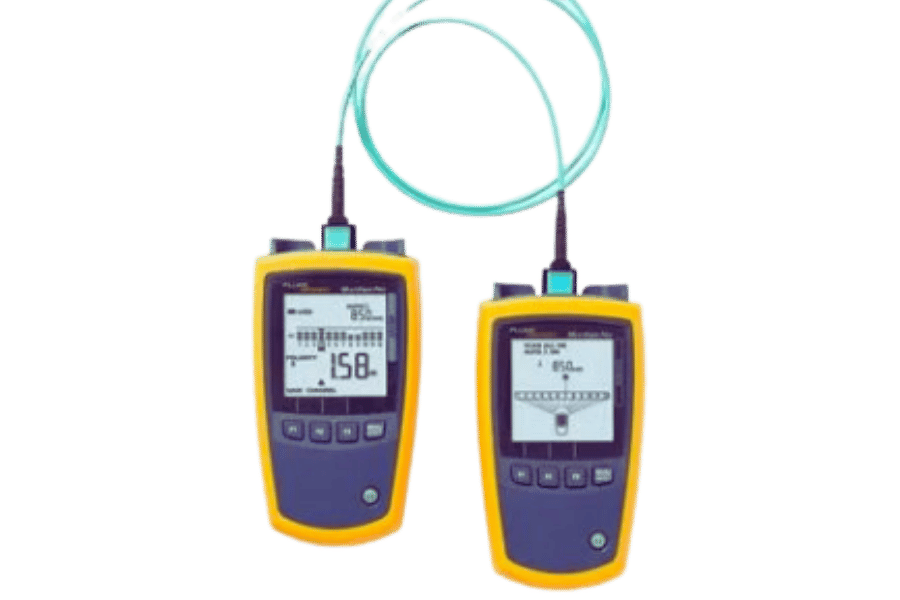
- Power Meter and Light Source Integration: The power meter is extremely valuable as it can be used with a built-in light source to fully cover all aspects of link testing, including checking the installed cables.
- Pass/Fail Analysis: The software included in the device also enables the detection of good and defective links in Fiber optics according to the set standards and principles, giving quick and timely information on performance parameters.
- Easy Navigation and Reporting: The advanced Windock M3 system incorporates state-of-the-art software solutions that permit engineers to maneuver the testing phase successfully without much hassle and produce extensive conclusions on all tests performed for documentation purposes.
It is only with the MultiFiber™ Pro Optical Power Meter that network engineers can efficiently, accurately, and reliably perform playful tests on MPO connectors due to the above guidelines.
Additional Accessories like MPO adapters
Apart from the MultiFiber™ Pro Optical Power Meter, certain accessories are required which will further make the testing and maintenance of MPO connectors more effective optimistic:
- MPO Adapters: Convent connectors are the most important accessories available for practical testing purposes and the interchange of MPO power and test cords. These include many types to suit the different mpo connectors and styles of connectors to allow testing devices to be efficiently incorporated.
- MPO Cleaning Tools: The MPO connectors and the ether adapters must be washed so as to take accurate readings for measurements. Many MPO cleaning accessories, like cassette cleaners or cleaning sticks, are practical tools due to their efficiency in cleaning dust from the end faces of connectors.
- Reference Cables: Checking whether correct calibration levels are used to power the power meter requires good-quality test reference cables. These reference cables include factory terminations to reduce insertion loss and enhance termination performance during orthogonal testing.
- Attenuators: MPOs can have a variable power rating, usually in the range of 1 dB, to avoid excess power, which may burn them out when using fiber optic systems with excessive power capabilities. There are various reasons why this is essential, such as controlling the power level in the meter.
These additional accessories will maximize the versatility and reliability of the MultiFiber™ Pro Optical Power Meter, ensuring that the high-density fiber optic network is thoroughly and effectively tested.
Reference Sources
Frequently Asked Questions (FAQs)
Q: What is an MPO tester’s significance in Fiber Optic testing?
A: An MPO tester is a more specialized device mainly intended for the performance test of multiphoton users or MPO connectors within the fiber optic network. It’s important because it allows one to test the functionality and efficiency of MPO-terminated fibers without having to test each of the fourteen individual fibers, which is a much more tedious and painstaking process of fiber optic cable testing.
Q: How is an MPO tester suited for this application compared to a patchcord and traditional single-fiber testing methods?
A: An MPO tester differs from ordinary testers because it tests only one fiber and a single connector. This feature minimizes the time it takes to test and improves efficiency, especially when testing high-density fiber cable installations.
Q: What main features should you consider when buying an MPO tester?
A: Some determinants may include the scanner’s ability to automatically test 12 fibers in MPO connectors straight away, its ability to test, store, and transfer scanned test information, and suitability for the two types of lenses: Multimode fibers and singlemode fibers. These variations are equally available on some more complex models, like the Fluke Networks MultiFiber™ Pro.
Q: In what way does an MPO tester raise the efficiency of testing the quality of fiber optics?
A: An MPO tester increases the efficiency of the ud23Zat fiber optic tester by shortening the time spent conducting testing. It can assess numerous fibers simultaneously, though a picture of going from one fiber to another position on the tester’s fan-out cords is used. This is especially useful when carrying out the test on MPO fiber trunks or large-scale pieces of fiber optic systems.
Q: Can the MPO tester multimode and class modes be used?
A: Yes, there are various MPO testers these days that allow the use of multimode and singlemode fibers. For instance, some kits have a MultiFiber Pro power meter that can handle both fibers, which is useful for many situations.
Q: What distinguishes the MPO PON tester, a power meter, and a traditional light source?
A: Quite generally, considering a typical power meter and light source, such will always characterize one fiber in a tested state, whereas single fiber MPO connectors utilizing fiber optic connectors, an MPO tester can test numerous fibers simultaneously. This also gives greater efficiency to tests of high-density MPO connectors using MPO testers.
Q: How is the polarity managed with an MPO tester?
A: Ambient MPO testers sometimes have this functionality to change from A to B or C polarization in the multi-fiber connectors. This ensures that tests will be completed accurately even if there is an unusual polarity configuration, and test results won’t be affected by potential errors.
Q: What scenario describes situations where an MPO tester would be possible or expected to be used?
A: When it comes to female MPO enclosures, an MPO tester embeds a fiber performance assessment of each fiber included in the MPO connector, as well as an overall passing or failing outcome for the whole cable, which is decisive for understanding the single fiber test outcome. Some also offer a comprehensive assessment of the fiber link, making it easier to trace down the problem areas of the optical network.