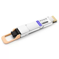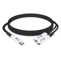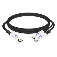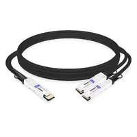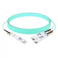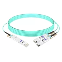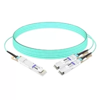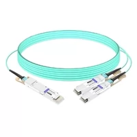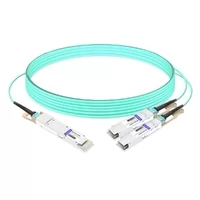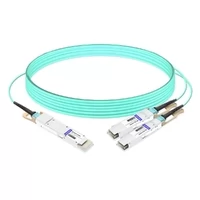

Four 400G ports, 1.6 Tbps of aggregate one-direction port bandwidth, and a compact chassis at an unusually accessible price. The hardware is compelling; optical interconnect costs can determine the total budget.
Four 400GbE ports delivering 1.6 Tbps of aggregate one-direction port bandwidth, in a half-width chassis you can lift with one hand. List price $1,295; street price around $1,100. That works out to under $0.70 per gigabit of aggregate port bandwidth — a number that, until recently, was difficult to imagine outside a hyperscaler’s volume contract.
The CRS804-4DDQ is therefore not interesting simply because it is fast. It is interesting because it moves 400G from “capital project” to “purchase order.”
But there is a catch, and it is not in the switch. Depending on the reach and module type, the four optics on the front panel can cost as much as — sometimes more than — the chassis they plug into. So this review covers both halves of the bill: what MikroTik shipped, what independent testing has measured, and how to select appropriate interconnects.
Key Takeaways
- 4× 400GbE QSFP56-DD, 1.6 Tbps aggregate port bandwidth, $1,295 list / ~$1,100 street.
- QSFP56-DD ports — do not assume OSFP or QSFP112 module compatibility.
- 1.589 Tbps with IxNetwork and 1.567 Tbps with CyPerf in independent testing.
- 29.3 W idle in independent testing; 123 W rated maximum; low-40 dBA noise without optics.
- Transceiver, cabling, and endpoint costs can outweigh the price of the switch.
Specs at a Glance
| Item | CRS804-4DDQ |
| High-speed ports | 4× 400GbE QSFP56-DD |
| Switching capacity | 1.6 Tbps aggregate one-direction port bandwidth |
| Management ports | 2× 1G/10G Ethernet (RJ45) |
| Console | 1× serial |
| Switching ASIC | Marvell 98DX7335A1 (Prestera, 5 nm, 32× 50G) |
| CPU | Annapurna Labs AL52400, quad-core |
| Memory | 4 GB DDR4 (ECC not confirmed by official specifications) |
| CPU ↔ ASIC link | 10 Gbps |
| Power supplies | 2× 350 W, redundant, hot-swap |
| Fans | 2× hot-swap |
| Idle / max power | 29.3 W tested idle / 123 W rated maximum |
| Chassis | 218 × 387 mm, 1U, half-width |
| OS | RouterOS v7 |
| List price | $1,295 (~$1,100 street) |
What $1,100 Buys You: The Hardware Tour
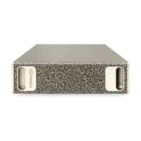
The first thing to understand is the shape. This is a half-width switch: 218 mm wide, but a full 387 mm deep. That depth is the one real ergonomic compromise. Half-width lab shelves are usually built around short-depth gear, and a 387 mm chassis occupies most of the available depth. Mounting two units side by side therefore requires planning rather than assumption. MikroTik offers a dual-rack kit that mounts two switches in a single 1U, but check your rack depth and cable bend radius before committing.
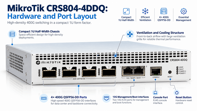
The front panel is dominated by four QSFP56-DD cages, each equipped with a substantial finned heatsink. This seemingly small detail becomes important when the ports are populated with 400G DR4 modules, whose thermal requirements must be matched to the switch’s cooling capabilities.
Also on the front panel are two 1G/10G RJ45 management ports, connected to the management processor rather than the switching ASIC, along with a serial console and reset button. This separation helps preserve management access when the data plane experiences problems. Rack-mounting accessories support both half-width and standard 19-inch installations.
At the rear, two 350 W Gospower supplies provide redundancy and hot-swap capability, alongside two hot-swappable fans. MikroTik rates the maximum power consumption at 123 W with attachments installed, comfortably below the capacity of a single power supply. The PSUs connect directly to the main PCB rather than through a separate wiring harness, providing a cleaner internal layout than some of the company’s lower-end models.
Inside the Chassis
Removing the two heatsinks reveals an unusually clean internal layout for a switch in this price category.
Under the smaller heatsink sits the 10GbE PHY associated with the management interfaces. Under the larger one is a quad-core Annapurna Labs AL52400 processor with 4 GB of DDR4 memory. A third-party teardown observed five DRAM packages, suggesting possible ECC support, although MikroTik’s official specifications do not explicitly confirm this capability.
The obvious question is whether that CPU makes the CRS804 a 1.6 Tbps firewall. It does not.
The Annapurna processor communicates with the switching ASIC over a single 10 Gbps link. Traffic that must be processed by the CPU, including CPU-handled NAT and stateful firewall operations, is constrained by this connection and the CPU’s processing capacity.
However, eligible Layer 3 traffic may be forwarded directly by the Marvell Prestera ASIC using hardware offloading, depending on the RouterOS configuration and supported features. Hardware-offloaded forwarding should therefore be distinguished from CPU-based routing and firewall processing.
This platform is best evaluated primarily as a high-speed Ethernet switch rather than a 400G stateful firewall.
The data plane itself is powered by a Marvell 98DX7335A1, a 32-lane, 50 Gbps Prestera switching ASIC manufactured using a 5 nm process. This merchant-silicon architecture is a major reason the CRS804 can provide high-throughput 400G switching at such an accessible price.
QSFP56-DD vs OSFP vs QSFP112: Pick the Right Port
This is where many first-time 400G buyers risk making expensive purchasing mistakes.
QSFP56-DD, QSFP112, and OSFP are all associated with high-speed Ethernet applications, but their mechanical and electrical interfaces are not automatically interchangeable.
| Form Factor | Lanes × Speed | Fits This Switch? | Backward Compatibility |
| QSFP56-DD | 8×50G PAM4 | Yes | Selected QSFP56, QSFP28, and QSFP+ modules, subject to host support |
| QSFP112 | 4×100G PAM4 | No — different host electrical architecture | Depends on host support |
| OSFP | 8×50G or 8×100G | No — different, larger cage | Depends on module and host platform |
The CRS804-4DDQ uses QSFP56-DD ports designed for 400G operation over eight 50G PAM4 electrical lanes.
QSFP112, by contrast, uses four electrical lanes operating at approximately 100G per lane. Although the naming and physical characteristics of different QSFP variants may appear similar, electrical lane mapping, firmware support, link modes, and module power requirements all determine actual compatibility.
OSFP modules use a different and larger mechanical form factor and cannot be inserted directly into QSFP56-DD cages.
Backward compatibility with earlier QSFP module generations also depends on the switch’s supported operating modes and module compatibility list. Mechanical compatibility alone does not guarantee successful link establishment.
As a purchasing rule: choose optical transceivers and cables explicitly supported for the CRS804-4DDQ. A QSFP-DD label alone is not sufficient proof of compatibility.
Breakout: Turning Four Ports into Sixteen
Four ports may seem limiting until you consider that each 400G port has eight independent 50G host-side electrical lanes.
MikroTik supports configurable breakout modes, allowing the available 400G bandwidth to be divided into smaller Ethernet interfaces when the appropriate link modes and interconnects are used.
| Configuration | Ports Delivered | Typical Use |
| 4×400G | 4 | GPU node interconnect, spine uplink |
| 8×200G | 8 | Compatible 200G NICs and uplinks |
| 16×100G | 16 | Existing 100G leaf switches, storage targets, 100G test equipment |
| 400G → 4×100G (compatible DR4 → 4×DR1) | 16 | Brownfield upgrades: retain 100G endpoints while introducing a 400G core |
The 100G breakout path is particularly useful when upgrading existing data center networks.
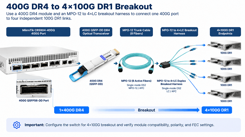
A 400G DR4 transceiver uses four optical transmit lanes and four optical receive lanes, requiring eight fibers within an MPO-12 connector. Four 100G DR1 links likewise require four duplex fiber pairs, totaling eight fibers.
With compatible optical modules, an MPO-12-to-4×LC breakout harness can connect one 400G DR4 interface to four independent 100G DR1 optical endpoints.
However, the harness itself only provides the physical fiber breakout. The switch must also be configured for 4×100G operation, and the optical modules, FEC settings, interface modes, and link partners must be compatible.
This distinction matters: a physical breakout cable does not automatically create four operational Ethernet interfaces.
With the correct configuration, the CRS804 can serve as a compact 400G aggregation platform while allowing existing 100G servers, storage devices, and network equipment to remain in service during the migration.
Two practical cautions are worth emphasizing.
First, the breakout harness must match the optical module’s fiber polarity and connector requirements, including MPO guide-pin configuration and APC polish where specified. An UPC-to-APC mismatch can cause excessive insertion loss, increased reflectance, or unreliable link operation.
Second, each additional breakout connection introduces another potential point of failure. Document fiber polarity, port mapping, connector types, and link assignments before finalizing the cabling installation.
Management and RoCEv2
Management is standard MikroTik: RouterOS v7 provides configuration access through the CLI, WebFig browser interface, and WinBox desktop application.
These familiar management options make the CRS804 approachable for network administrators already working with MikroTik equipment.
For AI networking, one of the more important considerations is Priority Flow Control (PFC) and the broader set of congestion-management capabilities required by the intended workload.
The switch provides configurable flow-control features, and RouterOS exposes the interface and breakout configuration directly.
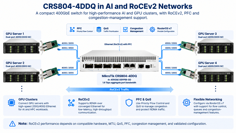
In independent testing, ServeTheHome reported using the CRS804 in an eight-node NVIDIA GB10 cluster running NCCL over an RDMA network.
That result is encouraging for compact AI and GPU interconnect deployments, but successful RDMA operation should not be interpreted as a guarantee of lossless performance under every traffic condition.
RoCEv2 deployments require careful validation of endpoint configuration, MTU, QoS mapping, PFC behavior, congestion-management features, and the specific RouterOS version.
PFC alone does not guarantee a lossless Ethernet fabric. Incorrect configuration can cause congestion propagation, reduced throughput, or other performance problems.
For teams without extensive RouterOS experience, AI-assisted tools can help interpret documentation, draft configuration commands, and simplify troubleshooting.
However, changes involving port modes, flow control, QoS, and congestion management should still be reviewed and validated by a qualified network operator.
AI assistance can lower the learning curve, but it does not replace engineering verification.
DGX Spark Cluster Builds with the CRS804-4DDQ
The MikroTik CRS804-4DDQ can serve as a compact 400GbE switch for small NVIDIA DGX Spark clusters. The key planning detail is the number of usable 200GbE endpoint links: each of the switch’s four 400G QSFP56-DD ports can be configured for supported breakout modes, including 2×200G.
Choose a DAC assembly that is explicitly compatible with both the CRS804 and the DGX Spark’s ConnectX-7 QSFP interface. Matching the headline data rate alone is not enough.
Four DGX Spark Systems: The Simplest Switched Topology
For a four-node cluster, connect one 200GbE ConnectX-7 link from each DGX Spark to a separate 200GbE switch interface. One cable per Spark is sufficient for this basic switched design, leaving the second QSFP port on each system unused.
NVIDIA Sync’s Cluster Assistant supports up to four DGX Spark systems connected through a switch, making this a practical starting point for a lab or development cluster.
Four-Node Bill of Materials
| Item | Quantity | Notes |
| NVIDIA DGX Spark | 4 | Use compatible DGX OS and software releases; matching memory configurations simplify planning. |
| MikroTik CRS804-4DDQ-hRM | 1 | Four 400G QSFP56-DD ports; configure the required 200G link mode. |
| 200G-capable DAC assemblies | 4 | One link per Spark. Verify connector type, lane mapping, FEC, and compatibility at both ends. |
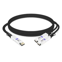
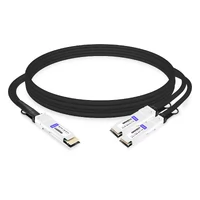
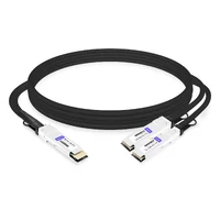
| Alternative breakout option | 2 assemblies | Two compatible 400G-to-2×200G breakout DACs can provide four 200G endpoint links across two switch ports. |
Do not order a cable solely by a description such as “400G QSFP-DD to 200G QSFP.” The switch-side and Spark-side connector implementations must both fit and support the intended electrical mode. Confirm the exact part number with the cable supplier and check the supported interface modes before deployment.
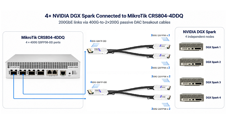
Verify the 200GbE Link Speed
Do not assume that every link will automatically negotiate to 200Gb/s. NVIDIA’s switched-cluster instructions warn that a link may come up at a lower speed. If it does, configure the relevant CRS804 interface for the supported 200G mode and disable auto-negotiation where required.
For CRS804 2×200G breakout operation, MikroTik specifies a forced speed mode with auto-negotiation disabled. A compatible DAC configuration may use the RouterOS speed mode 200G-baseCR4, but the exact interface name, FEC setting, and mode must match the cable and installed RouterOS release.
After configuring the switch, verify the link from both ends and confirm that each intended endpoint is operating at 200,000 Mb/s before running benchmarks. If performance is lower than expected, inspect the negotiated speed, FEC, MTU, interface mapping, and workload configuration before attributing the result to the switch or to a PCIe bandwidth limit.
Cluster Software and Validation
NVIDIA Sync’s Cluster Assistant can discover the supported topology, configure the ConnectX-7 network, plan IP addresses, check link performance, and establish inter-node SSH access. It does not install or configure distributed inference or training workloads.
After the network is ready, use the appropriate NVIDIA playbooks and software stack—for example, NCCL for communication testing, vLLM for supported inference deployments, or PyTorch workflows for fine-tuning.
For RoCEv2 workloads, validate MTU, FEC, QoS mapping, Priority Flow Control (PFC), congestion management, and the exact RouterOS version under representative traffic. PFC alone does not guarantee a lossless fabric, and successful link establishment is not the same as validated distributed-workload performance.
Expanding to Eight DGX Spark Systems: Use All Four 400G Ports
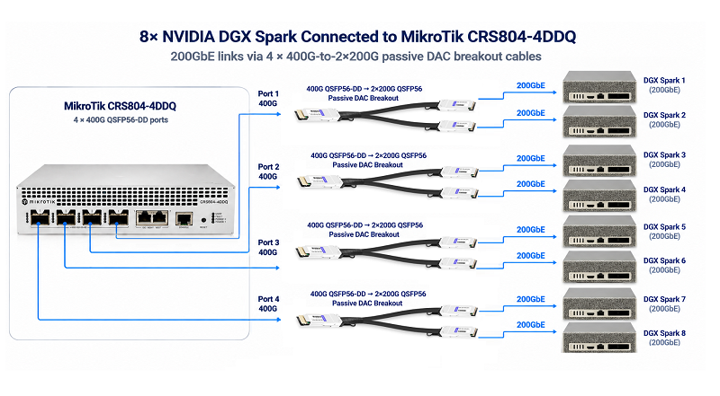
A CRS804 has four physical 400G ports. Configure each port for 2×200G breakout and the switch can expose up to eight independent 200GbE endpoint interfaces. That is enough to connect eight DGX Spark systems when each node uses one 200G link.
Eight-Node Breakout Topology
| CRS804 Physical Port | 200G Breakout Link A | 200G Breakout Link B |
| Port 1 | DGX Spark 1 | DGX Spark 2 |
| Port 2 | DGX Spark 3 | DGX Spark 4 |
| Port 3 | DGX Spark 5 | DGX Spark 6 |
| Port 4 | DGX Spark 7 | DGX Spark 8 |
This eight-node design requires four compatible 400G-to-2×200G breakout assemblies and eight 200G cable legs. It uses all four switch ports.
It is a single-link-per-node topology, not dual-link redundancy. Connecting both ConnectX-7 ports on all eight systems would require 16 independent 200G switch-side interfaces, more than one CRS804 can provide.
The NVIDIA Sync Cluster Assistant currently supports up to four DGX Spark systems through a switch, so it does not automate an eight-node topology. Configure the larger fabric manually using NVIDIA’s ConnectX-7 networking instructions, then verify port mapping, IP addressing, SSH, link speed, RoCEv2, and NCCL behavior across all nodes.
A breakout cable creates the physical links; it does not configure the cluster by itself.
What Can an Eight-Node DGX Spark Cluster Run?
Eight 128GB DGX Spark systems provide up to 1TB of aggregate unified system memory across the cluster and up to 8 PFLOPS of aggregate theoretical FP4 performance when calculated from NVIDIA’s per-system peak specification, which uses its stated sparsity assumption.
These are aggregate planning figures—not a single flat 1TB memory pool and not a guarantee of sustained application performance. The software must distribute model weights and workloads across nodes, and communication overhead can materially affect results.
Potential workloads include:
- Large-model inference: Run supported, quantized models across multiple nodes when compatible weights and model-parallel software are available. As a rough illustration, 1.6 trillion parameters at 4-bit precision require about 0.8TB for raw weights alone, before quantization metadata, KV cache, activations, and runtime overhead. Fitting and running a specific model is not guaranteed by aggregate memory capacity.
- Multi-model serving: Host separate inference services on different nodes or shard a larger model across the cluster. The number of concurrent 70B-class instances depends on quantization, context length, KV-cache requirements, and runtime overhead.
- Distributed LoRA/QLoRA experiments: Evaluate selected large models with a compatible framework, optimizer configuration, and validated memory budget rather than assuming a particular parameter count will be practical.
- AI research and engineering: Test MPI/NCCL communication, experiment with mixture-of-experts (MoE) designs, and prototype distributed inference, fine-tuning, or reinforcement-learning workflows.
- Private retrieval-augmented generation (RAG): Combine local embedding, retrieval, and inference services. Keeping data on-site also requires appropriate network, access-control, and application settings so sensitive information is not sent to external services.
Power Planning for Four- and Eight-Node Builds
For conservative circuit planning, use the 240W power-supply rating per DGX Spark and the CRS804’s 123W maximum rated consumption.
| Configuration | Calculation | Estimated Maximum Rated Load |
| 4 DGX Spark systems + 1 CRS804 | 4 × 240W + 123W | 1,083W |
| 8 DGX Spark systems + 1 CRS804 | 8 × 240W + 123W | 2,043W |
These are sizing estimates, not measured steady-state consumption, and exclude other equipment and power-conversion losses.
At 120V, the eight-node estimate is about 17A, above the nominal 1,800W capacity of a 120V/15A circuit. Do not assume that a standard 15A household circuit can support the full eight-node build.
Plan an appropriately rated circuit or suitable 208–240V supply, and confirm actual load and local electrical-code requirements with a qualified electrician. A four-node build has a lower estimated load, but it should still be checked against the circuit’s permitted continuous load.
Measured Performance
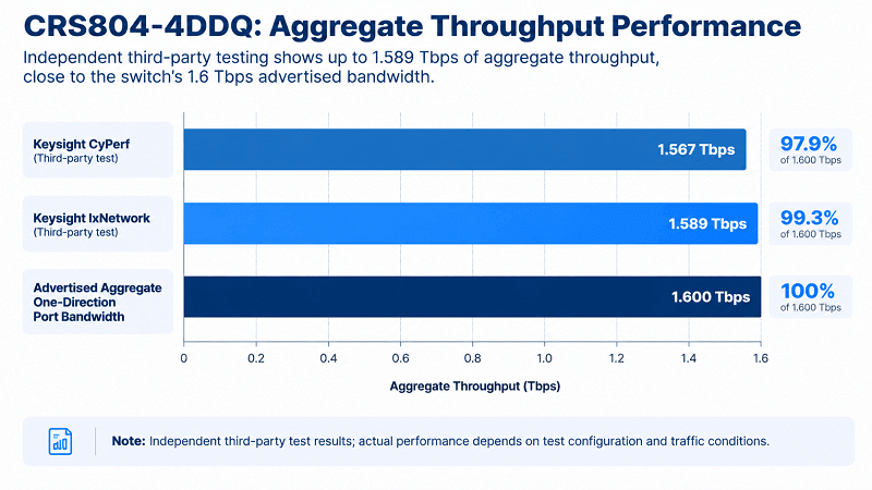
Independent testing published by ServeTheHome reported the following aggregate throughput results.
| Test | Result | Setup |
| Keysight CyPerf | 1.567 Tbps | 4×DR4 to 4×DR4 |
| Keysight IxNetwork | 1.589 Tbps | 4×DR4 → 16×DR1 (MPO-12-to-LC fanout) |
Source: ServeTheHome, Cheap Desktop 400GbE Switch MikroTik CRS804-4DDQ-hRM Review, September 3, 2026.
These figures are independent third-party measurements, not FiberMall laboratory test results.
The IxNetwork result is particularly interesting because the test achieved 1.589 Tbps of aggregate throughput using four 400G DR4 switch-side modules connected to sixteen 100G DR1 optical links.
This corresponds to approximately 99% of the switch’s advertised 1.6 Tbps aggregate one-direction port bandwidth under the reported test conditions.
The test demonstrates the potential of the CRS804’s 400G breakout capabilities. However, reproducing these results requires compatible traffic-generation equipment, transceivers, electrical PHY modes, FEC settings, and breakout configuration.
Actual production performance also depends on packet sizes, traffic patterns, interface settings, and enabled switch features.
For a chassis priced around $1,100, these third-party results indicate that the CRS804 can deliver impressive aggregate switching throughput for its price class.
Power, Noise, and Rack Mounting
ServeTheHome reported an idle power draw of approximately 29.3 W in its test configuration.
MikroTik specifies a maximum rated power consumption of 123 W with attachments and 92 W without attachments. These figures represent maximum rated consumption under different configurations, not measured idle power.
That distinction matters when comparing the CRS804 with larger data center switches.
Depending on the model and configuration, used 32-port 100GbE switches can consume 900 W or more and generate noise levels exceeding 50 dBA.
The CRS804’s lower power requirements make it attractive for smaller laboratories, edge installations, and compact high-speed network environments.
Noise, however, remains an important consideration.
Without optical modules installed, independent measurements place the CRS804 in the low-40 dBA range. Installing high-power 400G optics can increase fan speed and push the noise level above 50 dBA under certain operating conditions.
This is acceptable in many equipment rooms and laboratory racks but less suitable for a quiet office or a desk directly beside the user.
Rack mounting is flexible.
A single unit can be installed in a standard 19-inch rack using the appropriate mounting accessories, while a dual-rack kit allows two units to occupy a single 1U space.
One mechanical consideration is the distribution of weight toward the rear of the chassis, where the redundant power supplies are located.
When installing the switch in a lightweight open-frame rack, ensure that the rack is stable, properly secured, and able to support the equipment safely. Additional shelf support may be appropriate.
The Optics Bill Nobody Budgets For
Here is the arithmetic that actually determines the total cost of a 400G deployment.
A 400G port is not simply a port on a switch. It is part of a complete interconnect system that includes the switch interface, optical transceiver or cable assembly, physical cabling, and the network adapter or equipment at the other end.
In some deployments, the switching hardware may represent only a relatively small share of the overall link cost.
The following table illustrates relative cost differences among common 400G interconnect options, using passive DAC as a baseline.
These ratios are planning estimates rather than verified quotations. Actual pricing varies by vendor, reach, module specification, compatibility requirements, and order quantity.
| Option | Reach | Typical Use | Relative Cost / Port |
| 400G QSFP-DD passive DAC | 1–3 m | Same-rack node-to-switch | 1× baseline |
| 400G QSFP-DD AOC | 3–30 m | Adjacent racks, short inter-rack links | 2–4× |
| 400G DR4 (MPO-12, 8-fiber) | 500 m | Switch-to-switch, structured cabling | 8–20× |
| 400G FR4 (duplex LC) | 2 km | Cross-building, campus | 15–30× |
| 400G DR4 + 4×DR1 fanout | Up to 500 m, subject to link budget | 100G hosts connected to a 400G core | DR4 + harness + 4×DR1 |
The important lesson is that a relatively inexpensive 400G switch does not automatically mean an inexpensive 400G network.
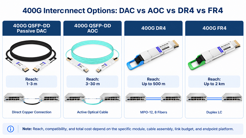
A four-port CRS804 populated with DR4 transceivers and MPO fiber trunks can require a substantially larger total investment than the chassis price alone suggests.
If the connected devices are located within the same rack, compatible passive DAC cables are often the most economical interconnect option.
They eliminate the need for separate optical transceivers and fiber patch cables while providing short-reach, high-bandwidth connectivity with minimal additional latency.
This is one of the deployment scenarios in which the CRS804’s price advantage becomes particularly attractive.
Three Ordering Notes That Prevent Returns
1. Match the host cage, not just the speed.
A 400G-capable host may use QSFP-DD or OSFP interfaces depending on its network adapter and hardware generation.
For example, certain high-speed NVIDIA ConnectX platforms use OSFP interfaces, while the CRS804-4DDQ uses QSFP56-DD.
Connecting these devices requires a cable assembly or optical transceiver solution compatible with both endpoints, including their electrical lane configurations, supported link speeds, FEC requirements, and physical connectors.
Do not assume that a passive form-factor adapter automatically resolves differences in electrical signaling or supported operating modes.
Before ordering, verify the complete host-to-switch interconnect configuration.
2. DR4 is not DR4 everywhere.
Although 400G DR4 defines a standardized optical interface, actual module implementations and deployment requirements must still be checked.
Confirm the number of active fibers, MPO connector type, polarity method, connector polish, supported breakout modes, and host compatibility.
A typical 400G DR4 interface uses eight active fibers within an MPO-12 connector, but the complete cable assembly must match the optical equipment.
3. Do not automatically buy 400G optics for a single 100G connection.
If the endpoint uses a 100G interface, a compatible QSFP28 transceiver operating in a supported 100G mode may provide a simpler solution than a 400G DR4 breakout configuration.
However, backward compatibility must be verified against MikroTik’s supported module list and the required port configuration.
Installing a single QSFP28 module in a compatible QSFP-DD cage does not create four independent physical QSFP28 sockets.
When four separate 100G DR1 endpoints must be connected through one 400G port, a supported 400G DR4 module with an appropriate MPO-to-LC breakout harness remains a practical option.
Planning Rule
Budget the complete optical link, not just the switch chassis.
Four 400G DR4 modules and their associated fiber infrastructure can cost more than the switch itself.
For short-distance links, a compatible passive DAC may deliver the required connectivity at a fraction of the overall optical interconnect cost.
Who Should Buy It — and Who Shouldn’t
Buy It If
- You have two or more accelerator nodes in the same rack and need a high-bandwidth 200G/400G Ethernet fabric with appropriately engineered congestion management, without investing in a much more expensive data center switch.
- You are building a compact storage network using technologies such as NVMe-oF or Ceph, where four 400G ports provide sufficient aggregation or spine connectivity.
- You need 400G networking in a laboratory or small deployment environment where high power consumption and excessive equipment noise are major constraints.
Skip It If
- You need more than four high-speed physical ports and require a scalable switching platform with additional native interfaces or a well-defined stacking architecture.
- You expect full line-rate stateful firewall or CPU-based routing performance. CPU-processed traffic is constrained by the 10 Gbps CPU-to-ASIC connection and CPU processing capacity, although eligible traffic may benefit from hardware offloading.
- You require native OSFP interfaces or are planning an 800G network architecture that demands a different electrical interface and switching platform.
FAQ
How much does the MikroTik CRS804-4DDQ cost?
The CRS804-4DDQ has a listed price of approximately $1,295, with reported street pricing around $1,100, depending on the reseller and market conditions.
At $1,100, the chassis price corresponds to approximately $0.69 per gigabit of its 1.6 Tbps aggregate one-direction port bandwidth, excluding optical modules and cabling.
Can I use OSFP or QSFP112 optics in the CRS804-4DDQ?
OSFP and QSFP112 modules should not be treated as compatible replacements for the CRS804’s QSFP56-DD modules.
The switch uses QSFP56-DD interfaces designed for eight 50G PAM4 electrical lanes at 400G.
OSFP requires a different mechanical cage, while QSFP112 uses a different four-lane electrical architecture.
Always check MikroTik’s supported module list and the specific optical module specifications before purchasing.
Can I break a 400G port into 100G links?
Yes. The CRS804 supports configurable breakout operation, including 4×100G and 2×200G modes.
For optical breakout, a compatible 400G DR4 module can connect to four 100G DR1 endpoints through an appropriate MPO-12-to-4×LC harness.
The switch must be configured for the required breakout mode, and the optical modules, FEC settings, and link partners must be compatible.
Is the CRS804-4DDQ loud?
Independent testing indicates noise levels in the low-40 dBA range without optical modules installed.
Noise can exceed 50 dBA when the switch operates with high-power 400G modules, depending on ambient temperature and cooling conditions.
It is generally more suitable for a laboratory rack or equipment room than a quiet desktop workspace.
Does it support RDMA / RoCEv2?
The CRS804 has been used successfully in third-party RDMA/NCCL testing involving a multi-node GPU cluster.
However, reliable RoCEv2 performance depends on the specific RouterOS version, supported congestion-management capabilities, MTU configuration, QoS policies, and endpoint settings.
PFC support alone does not guarantee lossless network operation. Deployment-specific validation is recommended.
Is a DAC enough, or do I need optics?
For short, compatible same-rack connections, a passive QSFP-DD DAC cable is often the lowest-cost option and introduces minimal additional latency.
For longer distances, AOC cables or optical transceivers may be more appropriate.
400G DR4 and FR4 modules are commonly used for structured fiber connections, with nominal reaches of 500 meters and 2 kilometers, respectively, subject to the optical link budget and equipment compatibility.
Choose the interconnect based on distance, host interface, supported link mode, cabling infrastructure, and total deployment cost.
Can the CRS804-4DDQ connect eight DGX Spark systems?
Yes. Configure all four 400G ports for 2×200G breakout and connect one 200G link to each of eight DGX Spark systems. This uses four breakout assemblies and does not provide two independent switch links per node.
Does NVIDIA Sync support an eight-node DGX Spark cluster?
The NVIDIA Sync Cluster Assistant supports up to four DGX Spark systems connected through a switch. An eight-node topology requires manual network configuration and validation before running NCCL, inference, or fine-tuning workloads.
Can an eight-node DGX Spark cluster run on a 120V/15A circuit?
Do not assume so. Using the 240W adapter rating for each Spark and 123W for the switch gives an estimated 2,043W, which exceeds the nominal 1,800W capacity of a 120V/15A circuit. Verify the actual load and consult a qualified electrician.
Does 1TB of aggregate memory guarantee that a 1.6T-parameter model will run?
No. Memory is distributed across the eight systems, and model sharding, compatible model weights, quantization overhead, KV cache, activations, framework support, and inter-node communication all affect whether a specific model can run efficiently.
Bottom Line
The CRS804-4DDQ does one thing that matters: it substantially lowers the entry cost of 400GbE networking.
Four 400G ports, 1.6 Tbps of aggregate one-direction port bandwidth, up to 1.589 Tbps reported in independent testing, approximately 29 W measured idle power, redundant power supplies, and hot-swappable fans make it an attractive option for compact high-speed networks.
It is not intended to replace a large-scale data center spine switch or a high-throughput stateful router, although it can serve as a compact spine or aggregation switch in smaller deployments.
For laboratories, storage networks, and small AI clusters that need affordable 400G connectivity, the CRS804 offers a compelling combination of bandwidth, flexibility, and price.
But the switch is only part of the investment.
The right optical transceivers, DAC or AOC cables, breakout assemblies, and endpoint interfaces determine whether a deployment remains cost-effective.
Budget the optics first. The switch is the inexpensive part.
Related Products:
-
 Mikrotik DDQ+85MP01D Compatible 400G QSFP-DD SR8 PAM4 850nm 100m OM4 MPO-16 DDM MMF Optical Transceiver Module
$149.00
-
MikroTik Compatible 50cm (1.6ft) 400G QSFP-DD to 2x200G QSFP56 PAM4 Passive Breakout Direct Attach Copper Cable
$90.00
-
MikroTik Compatible 1m (3ft) 400G QSFP-DD to 2x200G QSFP56 PAM4 Passive Breakout Direct Attach Copper Cable
$105.00
-
MikroTik Compatible 1.5m (5ft) 400G QSFP-DD to 2x200G QSFP56 PAM4 Passive Breakout Direct Attach Copper Cable
$115.00
-
MikroTik Compatible 2m (7ft) 400G QSFP-DD to 2x200G QSFP56 PAM4 Passive Breakout Direct Attach Copper Cable
$135.00
-
MikroTik Compatible 2.5m (8ft) 400G QSFP-DD to 2x200G QSFP56 PAM4 Passive Breakout Direct Attach Copper Cable
$150.00
-
MikroTik Compatible 3m (10ft) 400G QSFP-DD to 2x200G QSFP56 PAM4 Passive Breakout Direct Attach Copper Cable
$180.00
-
NVIDIA DGX Spark (940-54242-0006-000): Personal AI Desktop Supercomputer - Built on NVIDIA GB10 Grace Blackwell Superchip
$7800.00
-
MikroTik Compatible 3m (10ft) 400G QSFP-DD to 2x200G QSFP56 Breakout Active Optical Cable
$850.00
-
MikroTik Compatible 5m (16ft) 400G QSFP-DD to 2x200G QSFP56 Breakout Active Optical Cable
$858.00
-
MikroTik Compatible 10m (33ft) 400G QSFP-DD to 2x200G QSFP56 Breakout Active Optical Cable
$870.00
-
MikroTik Compatible 15m (49ft) 400G QSFP-DD to 2x200G QSFP56 Breakout Active Optical Cable
$898.00
-
MikroTik Compatible 20m (66ft) 400G QSFP-DD to 2x200G QSFP56 Breakout Active Optical Cable
$918.00
-
MikroTik Compatible 30m (98ft) 400G QSFP-DD to 2x200G QSFP56 Breakout Active Optical Cable
$958.00