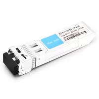
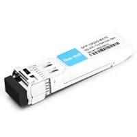
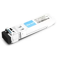
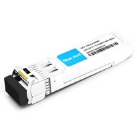
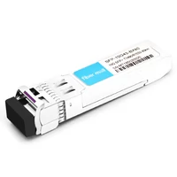
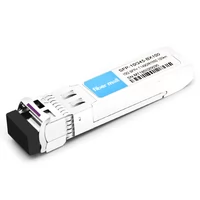
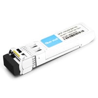
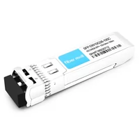
There are many kinds of 10G SFP + optical transceivers in the market, some optical transceivers can transmit 80km, and some others can transmit 100km, even 120km. Do you know the reason why the transmission distance is different? And why the long-distance optical receives, such as 80km 100km, and 120km optical transceivers, often burned down when we use them?
As we know the transmission distance of an optical transceiver is related to optical power and receiver sensitivity, However, dispersion is also an important factor that affects the transmission distance of optical transceivers.
Fiber loss α (dB/km) is one of the most important specifications of an optical fiber because it largely determines the maximum distance between a transmitter and receiver.
Therefore, users need to select an appropriate optical transceiver to meet their demands according to their networking situation. The actual transmission distance depends on the output power of the optical transceiver, the transmission attenuation of the optical fiber, and the receiver sensitivity of the optical transceiver.
Transmitter optical power and receiver sensitivity are important parameters to affect transmission distance.
Optical transceiver estimated transmission distance:
L (max) = (Output Power-Receiver Sensitivity) / α (dB/km)
|
Parameter |
Symbol |
Min |
Typical |
Max |
Unit |
Notes | |
|
Transmitter | |||||||
|
Centre Wavelength |
λc |
1530 |
1550 |
1565 |
nm |
| |
|
Side-Mode Suppression Ratio |
SMSR |
30 |
– |
|
dB |
| |
|
Average Output Power |
Pout |
0 |
|
+4.0 |
dBm |
1 | |
|
Extinction Ratio |
ER |
6.0 |
|
|
dB |
| |
|
Data Input Swing Differential |
VIN |
180 |
|
850 |
mV |
2 | |
|
Input Differential Impedance |
ZIN |
90 |
100 |
110 |
Ω |
| |
|
TX Disable |
Disable |
|
2.0 |
|
Vcc |
V |
|
|
Enable |
|
0 |
|
0.8 |
V |
| |
|
TX Fault |
Fault |
|
2.0 |
|
Vcc |
V |
|
|
Normal |
|
0 |
|
0.8 |
V |
| |
|
Receiver | |||||||
|
Centre Wavelength |
λc |
1260 |
|
1600 |
nm |
| |
|
Receiver Sensitivity |
|
|
|
-25 |
dBm |
3 | |
|
Receiver Overload |
|
-7 |
|
|
dBm |
3 | |
|
LOS De-Assert |
LOSD |
|
|
-26 |
dBm |
| |
|
LOS Assert |
LOSA |
-34 |
|
|
dBm |
| |
|
LOS Hysteresis |
|
0.5 |
|
4 |
dB |
| |
|
Data Output Swing Differential |
Vout |
300 |
|
900 |
mV |
4 | |
|
LOS |
High |
2.0 |
|
Vcc |
V |
| |
|
Low |
|
|
0.8 |
V |
| ||
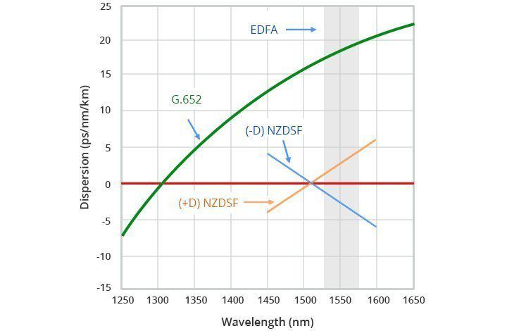
The main reason why the dispersion appears is that the speed of optical signals with the different wavelengths travel is different in the fiber. Then the optical signal with different wavelengths reaches the receiving end at a different time due to the accumulation of the transmission distance. After that, the pulse is widened, and then the signal values won’t be able to distinguish.
Signal dispersion is a consequence of factors such as intermodal dispersion, intramodal dispersion, polarization mode dispersion, and higher-order dispersion effects. The group velocity is the speed at which energy in a particular mode travels along with the fiber.
The dispersion coefficient is the arrival time difference between the two optical waves that have a wavelength interval of 1nm and a light wave transmission length of 1km, the unit is PS/nm km.
The relationship between dispersion and transmission rate.
The influence of group velocity dispersion on the specific ratio can introduce the criterion B △ T < 1, which does not produce the overlapping of adjacent pulses
B is the bit rate, △ t is the pulse broadening caused by group velocity dispersion
The higher the transmission rate is, the smaller dispersion should be controlled to ensure the transmission of the correct signal.
△T=DL δλ
L— transmission distance D—dispersion coefficient δλ— a light source of rms,-20dB spectrum width δλ-20,
δλ=δλ-20 /6.07
The typical dispersion value of G.652 fiber is 17ps / nm · km near the wavelength of 1550nm. After solving the attenuation problem of optical fiber, the dispersion limitation turns to the major problem that determines the transmission distance.
The dispersion tolerance of 10G SFP+ is 1600ps/nm (80km) and 2400ps/nm (120km).
Why are the optical transceiver of long-distance optical transceivers often damaged?
When the optical transceiver does not work, We usually need to check the DDM information of optical transceivers

First, we test the transmitter is normal, with no sensitivity in the receiver test, RX monitoring display is -3.12dBm when no optical input and the module working current is too large. We assumed that is caused by the APD abnormality based on the phenomenon in the preliminary detection. After that, use the multimeter to measure the APD voltage and display the abnormality.
According to the above test and analysis results, it is determined that APD can’t work normally due to the breakdown damage of large input power.
When removing the To case and observing it with a high-power microscope, we can see the APD has been damaged by the breakdown.
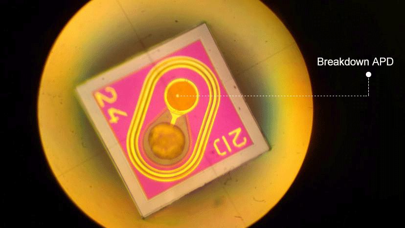
10G SFP + 80km receiver overload < – 7dBm. Please make sure the input power of APD is ≤ – 6dBm when using it. Optical power is too large which will cause the APD to break down instantaneously.
Summary
Review the following safety precautions to avoid injury and prevent damage to the optical transceiver.
1. We should protect the optical interface of the optical modules and optical fiber cable to prevent dust cross-contamination; before using, wipe up the end faces of the optical fiber cable with cleaning paper; When we uninstall the optical modules, immediately replace dust protective caps on the optical modules and optical fiber cables.
2. To prevent damage, while using the optical transceiver, we should pay attention to the plug-in method and strength of the optical fiber cable. The cable should be inserted in parallel and gently to avoid product damage by improper use.
3. We should pay attention to the output current and voltage of the instrument when using it. The working voltage ranges from 3.3 ± 0.5V. If the voltage exceeds the allowed working voltage or the voltage is unstable and the instantaneous pulse current is too large, It often causes optical module damage.
Related Products:
-
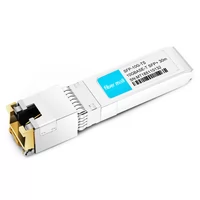
 SFP-10G-TS 10G Copper SFP+ 30m RJ45 Transceiver Module
$45.00
-
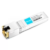
 SFP-10G-TS80 10GBase-T Copper SFP+ to RJ45 80m Transceiver Module
$55.00
-
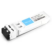
 SFP-10G55-ZR 10G SFP+ ZR 1550nm 80km LC SMF DDM Transceiver Module
$150.00
-
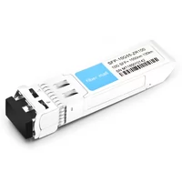
 SFP-10G55-ZR100 10G SFP+ ZR 1550nm 100km LC SMF DDM Transceiver Module
$280.00
-
 SFP-10G55-ZR120 10G SFP+ ZR 1550nm 120km LC SMF DDM Transceiver Module
$400.00
-
 SFP-10G23-BX70 10G BX SFP+ BIDI TX1270nm/RX1330nm 70km LC SMF DDM Transceiver Module
$100.00
-
 SFP-10G32-BX70 10G BX SFP+ BIDI TX1330nm/RX1270nm 70km LC SMF DDM Transceiver Module
$100.00
-
 SFP-10G54-BX80 10G BX SFP+ BIDI TX1550nm/RX1490nm 80km LC SMF DDM Transceiver Module
$300.00
-
 SFP-10G45-BX80 10G BX SFP+ BIDI TX1490nm/RX1550nm 80km LC SMF DDM Transceiver Module
$300.00
-
 SFP-10G45-BX100 10G BX SFP+ BIDI TX1490nm/RX1550nm 100km LC SMF DDM Transceiver Module
$650.00
-
 SFP-10G54-BX100 10G BX SFP+ BIDI TX1550nm/RX1490nm 100km LC SMF DDM Transceiver Module
$650.00
-
 SFP-DW10G28-100C 10G DWDM SFP+ C28 100GHz 1554.94nm 100km LC SMF DDM Transceiver Module
$235.00

