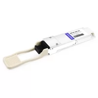
The question of how to efficiently manage massive data flows is the most critical challenge facing modern data center architects. As cloud computing, Internet of Things (IoT) deployments, and streaming services scale exponentially, the demand for bandwidth has reached unprecedented levels. While enterprise networks are continuously evaluating next-generation speeds, 100 Gigabit Ethernet (100GbE) remains the foundational backbone for the vast majority of today’s networking infrastructure. At the heart of this 100G revolution is the QSFP28 SR4 optical transceiver module.
The QSFP28 SR4 addresses the immediate issues surrounding high-speed data communication system designs, especially for high-density Top-of-Rack (ToR) and Spine-Leaf architectures. This highly efficient, relatively inexpensive, and ultra-reliable module provides robust connections of up to 100 gigabits per second (Gbps) over multi-mode fiber (MMF).
In this comprehensive guide, we will explore every technical facet of the QSFP28 SR4. We will decode its engineering, evaluate its performance criteria, provide actionable deployment strategies, and compare its capabilities against emerging high-speed standards like the OSFP form factor to help you plan your long-term network evolution.
Decoding the QSFP28 SR4 Technology
To truly leverage the QSFP28 SR4, network engineers must first understand the nomenclature and the physical engineering that drives its performance.
What Does “QSFP28 SR4” Mean?
The name of the module itself describes its exact function and form factor:
- Q (Quad): Indicates that the module utilizes four independent lanes for transmission and four for receiving.
- SFP (Small Form-factor Pluggable): Refers to the modular, hot-swappable physical footprint of the device, which is an industry standard for network hardware.
- 28: Represents the maximum data rate per lane. While typically running at 25 Gbps for 100G Ethernet, the electrical lanes are engineered to handle up to 28 Gbps to accommodate overhead and Forward Error Correction (FEC).
- SR (Short Reach): Denotes that the module is optimized for short-distance transmission, typically restricted to the confines of a single data center building or server room.
- 4: Re-emphasizes the use of 4 lanes (4 x 25G = 100G).
The Physical Engineering and Mechanics
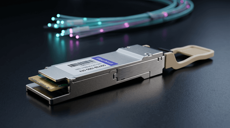
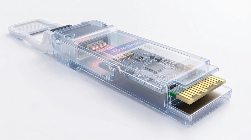
The QSFP28 SR4 transceiver transforms electrical signals from a network switch into optical signals, and vice versa. It is designed with a gold-finger edge, which serves as the highly conductive insertion side that connects directly to the switch port’s internal logic board. On the external-facing side, the module features a pull-tab mechanism (often color-coded beige or black for multimode applications) that must face outward to facilitate safe extraction without damaging the high-density port arrays.
Inside the module casing, the transceiver utilizes advanced semiconductor optics—specifically, Vertical-Cavity Surface-Emitting Lasers (VCSEL). VCSEL technology is the key to providing an effective and economical solution for short-reach, high-bandwidth communication. These lasers emit optical signals vertically from the surface of the semiconductor chip, allowing for easier coupling into optical fibers and significantly reducing manufacturing costs compared to edge-emitting lasers used in single-mode transceivers.
The Advantage of 850nm Wavelength and Multi-Mode Fiber (MMF)
The QSFP28 SR4 is strictly designed to operate at a central wavelength of 850nm over Multi-Mode Fiber (MMF). But why is this specific combination so ubiquitous in data centers?
1. Cost-Effective Scaling
When compared to longer wavelengths (such as 1310nm or 1550nm) found in Single-Mode Fiber (SMF) applications, the 850nm wavelength range is vastly more cost-effective. VCSEL lasers are cheaper to produce and test than the Silicon Photonics or Fabry-Perot lasers required for single-mode transmission. Furthermore, multi-mode fiber cables themselves are less expensive to manufacture and terminate, making the overall cost per 100G link highly favorable for high-density deployments.
2. Optimal Short-Range Performance and Modal Dispersion
Multi-mode fibers, particularly Laser-Optimized OM3 and OM4 cables, feature a larger core diameter (typically 50 micrometers). This large core allows multiple light paths (modes) to travel simultaneously. While this causes modal dispersion over long distances (which corrupts the signal), at 850nm within short distances (under 100 meters), dispersion is strictly controlled. The QSFP28 SR4 ensures minimal modal dispersion and superior signal integrity within these confined data center distances.
3. Maximum Transmission Distances
To achieve peak performance, selecting the correct MMF generation is critical:
- OM3 Fiber: Supports 100G transmission up to 70 meters. Suitable for intra-rack or adjacent-rack connectivity.
- OM4 Fiber: Supports 100G transmission up to 100 meters. This is the standard recommendation for modern QSFP28 SR4 deployments, providing enough reach for End-of-Row (EoR) or Top-of-Rack (ToR) to Spine switch connections.
- OM5 Fiber (Wideband MMF): While OM5 can support QSFP28 SR4 up to 100 meters, its primary benefit is for SWDM4 (Short Wavelength Division Multiplexing) applications. Using OM5 with a standard SR4 module will work perfectly, but it does not significantly increase the distance beyond what OM4 provides.
Architecting the Network: 100GBASE-SR4 and Breakout Applications
One of the most powerful features of the QSFP28 SR4 is its parallel optical architecture. Because the module transmits data over four separate 25G lanes, it opens up highly flexible network topologies.
The Standard 100G to 100G Connection
In a standard deployment, a QSFP28 SR4 module in Switch A is connected to a QSFP28 SR4 module in Switch B using a standard MPO/MTP-12 cable. The MPO-12 cable has 12 fiber strands, but the SR4 protocol only uses 8 of them: 4 strands for transmitting (Tx) and 4 strands for receiving (Rx), leaving the central 4 strands unused. This provides a direct, low-latency 100 Gbps pipeline between high-capacity routing equipment.
The 100G to 4x 25G Breakout Architecture
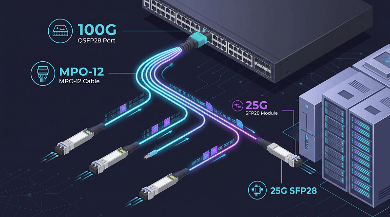
Data center real estate and port density are premium commodities. The QSFP28 SR4 excels in breakout scenarios where a single 100G port on a spine or core switch needs to distribute data to four separate 25G servers or leaf switches.
By using an MPO-to-4x-LC breakout cable, the optical signal is physically split. The MPO connector plugs into the QSFP28 SR4, while the other end of the cable terminates in four separate duplex LC connectors. Each LC duplex pair delivers a dedicated 25 Gbps link (using 25GBASE-SR SFP28 transceivers at the server end). This allows network architects to maximize switch port utilization, reducing the total hardware footprint and significantly lowering capital expenditures.
Future-Proofing: QSFP28 vs. QSFP-DD vs. OSFP Form Factors
While the QSFP28 SR4 is the undisputed king of 100G, artificial intelligence, machine learning, and hyperscale workloads are pushing networks toward 400G, 800G, and even 1.6T speeds. To understand where the QSFP28 fits, we must compare it to the next-generation form factors: QSFP-DD and OSFP.
The abbreviation OSFP represents the term Octal Small Form-factor Pluggable. The “octal” designation refers to its eight electrical lanes, a direct upgrade from the four lanes used in the QSFP28.
Physical and Thermal Comparisons
Thermal management is the defining constraint of modern networking. The QSFP28 SR4 is highly efficient, typically consuming less than 3.5 Watts of power per module. This makes cooling standard 100G switches relatively simple.
However, as speeds increase, heat becomes a critical issue. The OSFP MSA (Multi-Source Agreement) group developed the OSFP form factor specifically to solve thermal and density problems that earlier designs could not manage.
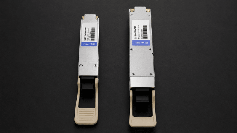
- QSFP-DD and QSFP28: The QSFP-DD shares a similar physical width with the legacy QSFP28 at 18.35mm. This allows QSFP-DD switches to offer backward compatibility, meaning you can often plug a 100G QSFP28 SR4 into a QSFP-DD port.
- OSFP: The OSFP device measures 22mm in width, which makes it bigger than QSFP-DD. The additional space works to improve thermal performance, which enables 800G and 1.6T speeds to function effectively.
Power Consumption and Lane Speeds
While your current QSFP28 SR4 runs 4 lanes at 25G (NRZ modulation), the future is significantly more robust. For 400G OSFP modules, each of the eight lanes runs at 50G using PAM4 modulation. For 800G, those lanes double to 100G each. At the bleeding edge of 1.6T, you’re looking at 200G per lane.
Power consumption scales aggressively with these speeds. While QSFP28 uses minimal power, OSFP modules in actual use case scenarios demonstrate power consumption between 8W and 12W for 400G, while their advanced models reach 15W for 800G. The actual power consumption of some 800G modules used in high-density installations approaches 20W.
The Strategic Takeaway: If you are upgrading an existing data center, 100G QSFP28 SR4 modules remain the most cost-effective solution for standard enterprise traffic. If you are building an AI/ML training cluster from scratch, OSFP gives you superior thermal headroom for high-power 800G and 1.6T modules, making it the preferred choice for new hyperscale builds.
Ensuring Compatibility: Multi-Source Agreement (MSA) and DDM
The Importance of the QSFP28 MSA
The Multi-Source Agreement (MSA) is a foundational document established by a consortium of manufacturers to standardize the physical dimensions, electrical interfaces, and signaling protocols of transceivers.
Conforming to the MSA is crucial for both manufacturers and consumers. For the QSFP28 SR4, MSA compliance guarantees that devices made by various vendors will be able to operate together seamlessly. This means a network architect can purchase a third-party QSFP28 SR4 module and install it in a Cisco, Juniper, or Arista switch with confidence. This ecosystem prevents vendor lock-in, drives competition, and significantly lowers the cost of 100G deployments.
Digital Diagnostics Monitoring (DDM/DOM)
Digital Diagnostics Monitoring (DDM), also known as Digital Optical Monitoring (DOM), is a critical embedded feature in professional-grade QSFP28 SR4 modules. Accessed via a standardized I2C interface, DDM allows network administrators to read real-time telemetry from the transceiver.
Core DDM metrics include:
- Operating Temperature: Monitoring internal thermal states to prevent overheating.
- Transceiver Supply Voltage: Ensuring the switch is providing stable power to the module.
- Laser Bias Current: An aging VCSEL laser requires more current to produce the same optical output. Monitoring bias current is the best way to predict a module’s end-of-life before it fails.
- Transmitted Optical Power (Tx): Verifying the module is sending a strong enough signal.
- Received Optical Power (Rx): Ensuring the module is receiving an adequate signal, which helps identify damaged fiber cables or dirty connectors.
By importing DDM data into network management software (like SolarWinds or PRTG), engineers can set automated alerts. For example, if the Rx power drops below a certain dBm threshold, the system flags the link for maintenance before packet loss impacts application performance.
Best Practices for Deployment and Cable Management
Deploying QSFP28 SR4 transceivers at scale requires strict adherence to physical layer best practices. Even minor physical imperfections can severely degrade a 100G link.
1. Fiber Inspection and Cleaning
The number one cause of optical link failure is microscopic dirt and debris on the fiber end-face. A single particle of dust on an MPO connector can block multiple 25G lanes, causing total link failure.
- Always use an MPO microscope to inspect the fiber end-face before insertion.
- Always clean the MPO cable using a specialized “click-cleaner” designed for MTP/MPO interfaces immediately prior to plugging it into the QSFP28 SR4.
- Never remove the protective dust cap from the transceiver until the exact moment you are ready to insert the fiber cable.

2. MPO Polarity and Pinning
MPO cables used with QSFP28 SR4 modules must strictly adhere to proper polarity standards (usually Type B polarity for direct transceiver-to-transceiver connections) to ensure that the Transmit (Tx) lasers align with the Receive (Rx) photodetectors on the opposite end. Furthermore, because the QSFP28 SR4 transceiver has built-in alignment pins (male), the MPO cable patching into it must be unpinned (female) to avoid physically crushing the optical array.
3. Bend Radius and Strain Relief
Multi-mode fiber carrying 100G payloads is susceptible to macro-bending losses. If an OM4 cable is bent too sharply, the light escapes the fiber core, leading to instant signal degradation. Ensure all cable trays and rack management systems maintain the manufacturer-specified minimum bend radius. Use velcro ties instead of zip-ties to avoid crushing the fiber jacket.
Troubleshooting Common QSFP28 SR4 Issues
Even with perfect planning, networking issues occur. Here is a systematic approach to troubleshooting a failing QSFP28 SR4 link:
Symptom 1: The Port Remains “Down” or Does Not Illuminate
Action: Check the switch OS logs. Is the transceiver recognized? If the switch outputs an “Unsupported Transceiver” error, you may need to enter a command (such as service unsupported-transceiver go in Cisco environments) to allow third-party MSA modules.
Action: Verify cable polarity. Ensure you are using a Type B MPO cable for direct connections so that Tx routes to Rx.
Symptom 2: High Bit Error Rate (BER) or Packet Loss
Action: Check the DOM/DDM statistics. If the Received (Rx) power is dangerously low (e.g., below -10 dBm), the signal is too weak.
Action: Clean the connectors. Unplug the MPO cable, use an MPO click-cleaner, and re-seat the connection.
Action: Check the cable length. Ensure you have not exceeded 100 meters on OM4 fiber or 70 meters on OM3 fiber.
Symptom 3: Intermittent Flapping (Port Goes Up and Down)
Action: Check the physical seating of the module. Ensure the module is pushed firmly into the switch and the extraction tab is locked.
Action: Monitor the transceiver temperature via DDM. If the module is exceeding 70°C, thermal throttling or failure may be occurring. Check rack airflow and fan status.
The Future of 100G and Market Dynamics
Despite the rapid advancement of 400G and 800G technologies driven by hyperscalers, the market for the QSFP28 SR4 remains incredibly strong. Several factors guarantee its relevance for the next decade:
- Enterprise Data Center Upgrades: Many traditional corporate networks are currently migrating from 10G/40G backbones to 100G backbones. The QSFP28 SR4 is the primary vehicle for this migration.
- Edge Computing: As IoT expands, computing power is moving to the edge. Edge data centers require high throughput but are highly cost-sensitive. The maturity and low price point of the QSFP28 SR4 make it ideal for edge deployments.
- 5G Infrastructure: Telecommunications providers utilize vast amounts of 100G links to backhaul traffic from 5G base stations to central switching hubs.
In summary, while technologies like the 1.6T OSFP will dominate AI research clusters, the QSFP28 SR4 provides the ultimate balance of reliable throughput, cost efficiency, and proven stability for the broader global network infrastructure.
Comprehensive Frequently Asked Questions (FAQs)
Q: What is a QSFP28 SR4 optical transceiver module?
A: The QSFP28 SR4 optical transceiver module is a compact, high-speed, and high-density module used to support 100G Ethernet applications. It utilizes multi-mode fiber to transmit data at 100 Gbps over short distances up to 100 meters.
Q: Can I use single-mode fiber (SMF) with a QSFP28 SR4?
A: No. The SR4 is explicitly engineered with 850nm VCSEL lasers designed for Multi-Mode Fiber (MMF). Using SMF will result in a total failure to link, as the microscopic core of single-mode fiber cannot properly capture the wide light spread of an 850nm VCSEL. For SMF, you need a QSFP28 LR4 or DR1 module.
Q: How does the QSFP28 SR4 transceiver work with breakout cables?
A: The QSFP28 SR4 transmits over four parallel 25G lanes. It is fully compatible with MPO-to-4x-LC breakout cables. This cable physically divides the 100G signal into four separate 25G signals, allowing you to connect one 100G switch port to four individual 25G server NICs or Top-of-Rack switches.
Q: What type of fiber cabling is used alongside the 100G QSFP28 SR4 transceiver?
A: The industry standard is OM4 multi-mode fiber utilizing an MPO-12 (or MTP-12) connector. This setup supports the maximum transmission distance of 100 meters. Older OM3 fiber can be used, but the maximum distance drops to 70 meters.
Q: Does the QSFP28 SR4 support FEC (Forward Error Correction)?
A: Yes, to ensure zero packet loss and a healthy Bit Error Rate (BER) at 100G speeds, the host switch generally enables RS-FEC (Reed-Solomon Forward Error Correction) on the port housing the QSFP28 SR4.
Q: Are there specific standards that the QSFP28 optical transceiver module complies with?
A: Yes, the module strictly abides by the IEEE 802.3bm 100GBASE-SR4 standard for optical characteristics and the SFF-8665 standard for the physical dimensions and electrical interface (the MSA).
Q: Can Cisco, Arista, and Juniper devices be connected using third-party QSFP28 modules?
A: Yes. As long as the transceiver is fully MSA-compliant, it can interface with major OEM hardware. However, you must ensure the third-party optics are correctly coded for the specific OEM switch to avoid software blocks.
Q: Are there any available diagnostic features embedded in the 100G-SR4 transceiver?
A: Yes. Digital Diagnostics Monitoring (DDM) is embedded within the transceiver. This provides real-time access to operational temperature, supply voltage, laser bias current, and both input and output optical power levels. These metrics are vital for network maintenance and troubleshooting.
Q: How does QSFP28 SR4 power consumption compare to next-generation modules?
A: QSFP28 SR4 modules are highly efficient, utilizing approximately 2.5W to 3.5W per module. By comparison, newer form factors like OSFP modules running at 400G consume 8-12W, and 800G OSFP modules consume 12-15W. The QSFP28 remains the most power-efficient choice for 100G data rates.
Q: Can I plug a QSFP28 SR4 into a QSFP-DD 400G port?
A: In most modern switches, yes. The QSFP-DD port design is backward compatible with legacy QSFP28 modules. The switch will automatically recognize the module and negotiate the port speed down to 100G. However, you cannot plug an OSFP module into a QSFP-DD port because OSFP modules and QSFP-DD ports have different physical sizes.