Virtual Local Area Networks (VLANs) are a traditional method of network virtualization that segment physical networks into multiple logical subnets for isolation and management. However, VLANs have notable limitations in several areas:
- Scalability Constraints: VLANs use a 12-bit identifier (VLAN ID), supporting a maximum of 4,096 VLANs. This limitation becomes evident in large-scale data centers and multi-tenant environments, failing to meet the growing network demands.
- Complexity of Connecting Across Physical Networks: VLANs are primarily designed for single broadcast domains. Connecting across physical networks requires complex configurations and additional protocol support, such as VLAN Trunking Protocol (VTP) or Multiple Spanning Tree Protocol (MSTP).
- Network Isolation and Security: In multi-tenant environments, VLAN isolation relies on managing and configuring VLAN IDs. Misconfigurations can lead to traffic leaks or security vulnerabilities between different tenants.
- Lack of Flexibility: The static configuration of VLANs restricts dynamic network adjustments and rapid responses to changing business needs and network topologies.
To address the limitations of traditional VLANs in terms of scalability, flexibility, and cross-physical network connectivity, Virtual Extensible LAN (VXLAN) was developed.
VXLAN is a network virtualization technology designed to create virtual Layer 2 networks over existing Layer 3 network infrastructures, enabling large-scale, flexible, and efficient network architectures.
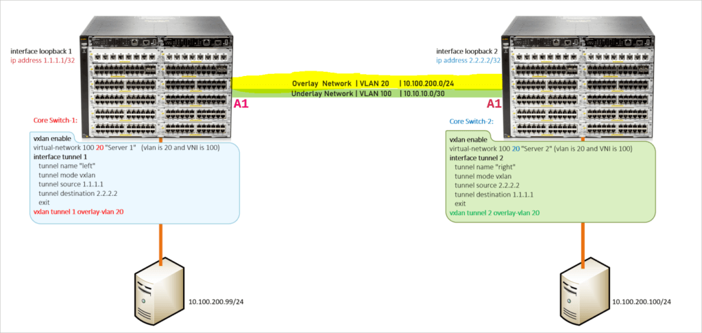
VXLAN Basics
VXLAN, or Virtual Extensible LAN, addresses the scalability and flexibility limitations of traditional VLANs in large-scale data centers and multi-tenant environments. VXLAN creates a virtual Layer 2 network over existing Layer 3 infrastructure, enabling virtual machine (VM) connectivity across physical network boundaries.
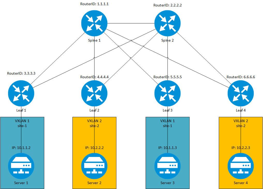
The core concept of VXLAN involves encapsulating Ethernet frames, originally transmitted in a Layer 2 network, within Layer 3 UDP (User Datagram Protocol) packets. This allows VMs to communicate across different physical servers, switches, and even data centers. This encapsulation mechanism not only enhances network scalability but also improves network isolation and security in multi-tenant environments.
VXLAN Working Principles
The core mechanism of VXLAN (Virtual Extensible LAN) involves encapsulation and decapsulation technology, encapsulating Layer 2 Ethernet frames within Layer 3 UDP packets for transmission. The detailed process is as follows:
Encapsulation:
- Source: When a virtual machine (VM1) sends an Ethernet frame, the frame is first transmitted to the VXLAN Tunnel Endpoint (VTEP).
- VTEP Processing: The VTEP encapsulates the original Layer 2 Ethernet frame in a VXLAN header. The VXLAN header includes a 24-bit VXLAN Network Identifier (VNI) to identify different VXLAN networks.
- UDP Encapsulation: The VXLAN header is then encapsulated in a UDP packet, typically using port 4789 (the default port for VXLAN).
- Layer 3 Transmission: The encapsulated UDP packet is transmitted through the existing Layer 3 network infrastructure (such as an IP network).
Decapsulation:
- Destination: Upon arrival at the destination VTEP, the VTEP decapsulates the UDP packet, extracting the original Layer 2 Ethernet frame.
- Transmission to Target VM: The decapsulated Ethernet frame is transmitted to the target virtual machine (VM2), enabling communication across physical networks.
VXLAN Header Structure

- Flags: Usually set to 0x08, indicating VXLAN encapsulation.
- VNI: Identifies different VXLAN networks, enabling network isolation in multi-tenant environments.
VXLAN Tunnel Endpoint (VTEP)
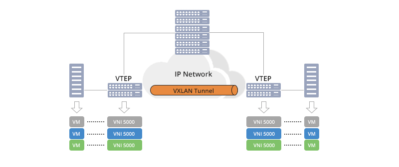
The VTEP is a critical component in the VXLAN architecture, responsible for VXLAN encapsulation and decapsulation operations. VTEPs can be deployed on physical switches, virtual switches, or dedicated network devices. Each VTEP has one or more Layer 3 interfaces (such as Loopback interfaces) for communicating with the physical network, while also connecting to virtual switches or virtual machines for handling Layer 2 network traffic.
The main functions of VTEPs include:
- Encapsulation and Decapsulation: Encapsulating Layer 2 Ethernet frames in VXLAN headers for Layer 3 transmission and decapsulating them at the receiving end to restore the original Ethernet frames.
- Network Identifier Management: Identifying and isolating different VXLAN networks based on VNIs.
- Routing and Forwarding: In Layer 3 VXLAN (L3 VXLAN), VTEPs also handle communication across subnets or data centers based on routing protocols.
VXLAN Control Plane
The VXLAN control plane is responsible for managing and distributing network information among VTEPs (VXLAN Tunnel Endpoints), ensuring the connectivity and consistency of the virtual network. Common VXLAN control plane protocols include:
Multicast Mode Based on IGMP (Internet Group Management Protocol):
- Uses IP multicast to distribute VXLAN traffic, suitable for simple network environments.
- Relatively simple configuration but may face complexity in multicast group management in large-scale deployments.
EVPN (Ethernet VPN):
- EVPN is a control plane protocol based on BGP (Border Gateway Protocol) that offers more efficient and flexible VXLAN traffic management.
- Supports MAC address learning and path selection in multi-tenant environments, making it suitable for large-scale and complex network architectures.
Core Advantages of VXLAN
High Scalability: VXLAN uses a 24-bit network identifier (VXLAN Network Identifier, VNI), supporting up to 16,777,216 VXLAN networks, significantly enhancing scalability to meet the needs of large-scale data centers and multi-tenant environments.
Flexible Connectivity Across Physical Networks: By encapsulating traffic over existing Layer 3 network infrastructure, VXLAN allows seamless connectivity of virtual machines across different physical servers, switches, or data centers.
Enhanced Network Isolation and Security: VXLAN provides finer-grained isolation mechanisms based on VNI, reducing traffic interference and security risks between different tenants or business units.
Support for Multi-Tenant Environments: VXLAN is designed with multi-tenant environments in mind, offering flexible network partitioning and isolation mechanisms to provide independent and secure virtual networks for different tenants.
Compatibility with Existing Network Architectures: VXLAN operates over existing Layer 3 network infrastructure without requiring extensive physical network modifications, reducing deployment costs and complexity.
VXLAN technology is mainly divided into Layer 2 VXLAN (L2 VXLAN) and Layer 3 VXLAN (L3 VXLAN). These two types of VXLAN differ significantly in functionality, architecture, and application scenarios, each suited to different network needs and environments.
Layer 2 VXLAN (L2 VXLAN)
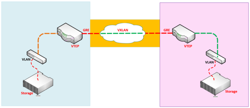
Layer 2 Virtual Extensible LAN (L2 VXLAN) is a network virtualization technology designed to create virtual Layer 2 networks over existing Layer 3 infrastructures, enabling Layer 2 communication between virtual machines (VMs). L2 VXLAN allows multiple virtual networks (broadcast domains) to coexist on the same physical network infrastructure, providing functions similar to traditional Local Area Networks (LANs) but with higher scalability and flexibility.
Core Functions of L2 VXLAN
- Virtual Network Isolation: Achieves isolation between different virtual networks using the VXLAN Network Identifier (VNI), ensuring that traffic does not leak between different tenants or business units.
- Layer 2 Connectivity Across Physical Networks: Allows VMs to communicate at Layer 2 across different physical servers and switches without relying on traditional VLANs.
- Support for Multi-Tenant Environments: Enables each tenant to have an independent virtual network, ensuring traffic isolation and security between tenants.
- High Scalability: Uses 24-bit VNIs, supporting up to 16,777,216 virtual networks, greatly enhancing scalability compared to traditional VLANs.
- Simplified Network Management: Centralized control planes (such as EVPN) simplify the management and configuration of large-scale virtual networks.
Architecture Design of L2 VXLAN
The architecture of L2 VXLAN includes several key components:
- VXLAN Tunnel Endpoint (VTEP): Responsible for VXLAN encapsulation and decapsulation, connecting the virtual network to the physical network. VTEPs can be deployed on physical switches, virtual switches, or dedicated network devices.
- Physical Layer 3 Network: Carries the encapsulated VXLAN packets, leveraging the existing IP network infrastructure for transmission.
- VXLAN Network Identifier (VNI): Distinguishes between different virtual networks to achieve network isolation.
- Control Plane Protocol (such as EVPN): Manages and distributes network information among VTEPs, ensuring the connectivity and consistency of the virtual network.
In a typical L2 VXLAN architecture, VTEP1 and VTEP2 are connected through the physical Layer 3 network, allowing VM1 and VM2 to communicate at Layer 2 within the same VLAN (VLAN 10) and VNI (5000).
Configuration Example for Layer 2 VXLAN
Below is a configuration example for L2 VXLAN based on Cisco Nexus switches, demonstrating how to create a VNI, configure VTEP interfaces, map VLANs to VNIs, and add physical interfaces to VLANs. Suppose we have two data centers, each with a VTEP (VTEP1 and VTEP2), and we aim to create an L2 VXLAN between these data centers, allowing VMs (VM1 and VM2) in different data centers to communicate within the same virtual network (VNI 5000).
Configuration Steps
- Configure VNI (VXLAN Network Identifier)
First, configure the VNI on each VTEP to identify different VXLAN networks.
nve1
member vni 5000
ingress-replication protocol bgp
- Configure VTEP Interface
Configure the VTEP interface, including the source interface (typically a Loopback interface) and the association with the VNI.
interface nve1
no shutdown
source-interface loopback0
member vni 5000
ingress-replication protocol bgp
- Map VLAN to VNI
Map the physical VLAN to the corresponding VNI to ensure correct encapsulation and decapsulation of traffic.
vlan 10
name VM-Network
vn-segment 5000
- Add Physical Interface to VLAN
Configure the physical interface in trunk mode and allow the corresponding VLAN to pass through.
interface Ethernet1/1
description Trunk to Spine
switchport mode trunk
switchport trunk allowed vlan 10
- Configure BGP Routing Protocol
Configure BGP to support Ingress Replication for traffic replication between VTEPs.
router bgp 65000
address-family l2vpn evpn
neighbor 10.0.0.2 remote-as 65000
neighbor 10.0.0.2 activate
- Configure Loopback Interface
Configure the Loopback interface as the source interface for the VTEP, ensuring it has a stable Layer 3 IP address.
interface Loopback0
ip address 192.168.0.1/32
Complete Configuration Example
Below is the complete configuration example, integrating the above steps:
! Configure Loopback Interface
interface Loopback0
ip address 192.168.0.1/32
! Configure NVE Interface
interface nve1
no shutdown
source-interface loopback0
member vni 5000
ingress-replication protocol bgp
! Map VLAN to VNI
vlan 10
name VM-Network
vn-segment 5000
! Configure Physical Interface
interface Ethernet1/1
description Trunk to Spine
switchport mode trunk
switchport trunk allowed vlan 10
! Configure BGP Routing Protocol
router bgp 65000
address-family l2vpn evpn
neighbor 10.0.0.2 remote-as 65000
neighbor 10.0.0.2 activate
Advantages and Disadvantages
Advantages
- High Scalability: L2 VXLAN supports up to 16,777,216 virtual networks using 24-bit VNI, far exceeding the 4,096 VLAN limit, making it suitable for large-scale data centers and multi-tenant environments.
- Flexible Network Isolation: Achieves fine-grained network isolation using VNIs, ensuring no traffic interference between different virtual networks, thus enhancing security.
- Layer 2 Connectivity Across Physical Networks: Allows VMs to communicate at Layer 2 across different physical servers and switches without relying on traditional VLAN protocols, simplifying configuration.
- Support for Multi-Tenant Environments: Each tenant can have an independent virtual network, ensuring traffic isolation and security, suitable for cloud service providers and large enterprises.
- Simplified Network Management: Centralized control planes (such as EVPN) simplify the management and configuration of large-scale virtual networks, reducing the risk of human error.
Disadvantages
- Higher Configuration Complexity: Compared to traditional VLANs, L2 VXLAN configuration involves VNI allocation, VTEP configuration, and control plane protocol (such as EVPN) deployment, making management and maintenance more complex.
- Dependence on Control Plane Protocols: L2 VXLAN typically relies on control plane protocols like EVPN to manage network information among VTEPs, adding to network architecture complexity.
- Broadcast Storm Risk: As L2 VXLAN supports Layer 2 broadcast traffic, ineffective control mechanisms can lead to broadcast storms, affecting network performance and stability.
- Network Visibility and Troubleshooting Difficulties: VXLAN adds an extra encapsulation layer, complicating network visibility and troubleshooting, necessitating specialized network monitoring and analysis tools.
- Hardware Requirements: High-performance network devices supporting VXLAN are usually required for efficient encapsulation and decapsulation, increasing hardware costs.
Layer 3 VXLAN (L3 VXLAN)
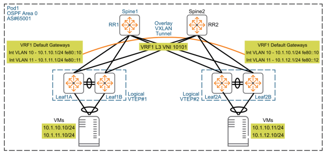
Layer 3 Virtual Extensible LAN (L3 VXLAN) is an advanced network virtualization technology designed to create virtual Layer 3 networks over existing Layer 3 infrastructures, enabling communication between virtual machines (VMs) across different subnets, data centers, or geographical locations. Unlike Layer 2 VXLAN (L2 VXLAN), L3 VXLAN supports both Layer 2 and Layer 3 communication by introducing routing mechanisms, allowing VMs to communicate efficiently across different broadcast domains.
Core Functions of L3 VXLAN
- Inter-Subnet Communication: L3 VXLAN allows VMs in different subnets to communicate via routing, making it suitable for complex network environments requiring inter-subnet or inter-location connectivity.
- High Scalability: By incorporating Layer 3 routing mechanisms, L3 VXLAN supports large-scale, multi-tenant network architectures, meeting the needs of enterprises and service providers.
- Geographic Redundancy and Disaster Recovery: L3 VXLAN supports virtual network connections across data centers and regions, enhancing network availability and disaster recovery capabilities.
- Enhanced Network Isolation and Security: Combining routing and VNI, L3 VXLAN provides finer-grained network isolation and security policies, ensuring traffic isolation in multi-tenant environments.
- Flexible Traffic Engineering: Introducing routing protocols and policies allows network administrators to flexibly manage and optimize network traffic, improving network performance and efficiency.
Architecture Design of L3 VXLAN
The architecture of L3 VXLAN is more complex than L2 VXLAN, encompassing the following key components:
- VXLAN Tunnel Endpoint (VTEP): In L3 VXLAN, VTEPs are responsible not only for VXLAN encapsulation and decapsulation but also for routing functions, handling inter-subnet traffic forwarding and routing decisions.
- Physical Layer 3 Network: Carries the encapsulated VXLAN packets, utilizing existing IP network infrastructure for transmission and supporting efficient routing and forwarding.
- VXLAN Network Identifier (VNI): Differentiates between virtual networks, achieving network isolation and multi-tenant support.
- Control Plane Protocol (such as EVPN): Manages and distributes routing information among VTEPs, ensuring connectivity and consistency across subnets and data centers.
- Routing Protocols (such as BGP, OSPF): Propagate routing information between VTEPs, facilitating traffic forwarding and routing decisions between different VNIs.
In a typical L3 VXLAN architecture, VTEP1 and VTEP2 are connected through the physical Layer 3 network and routers. VMs (VM1 and VM2) reside in different subnets (Subnet A and Subnet B) and communicate across subnets via L3 VXLAN.
Configuration Example for Layer 3 VXLAN
Below is a configuration example for L3 VXLAN based on Cisco Nexus switches, demonstrating how to create a VNI, configure VTEP interfaces, map VLANs to VNIs, configure routing protocols, and achieve inter-subnet communication. Suppose we have two data centers, each with a VTEP (VTEP1 and VTEP2), and we aim to create an L3 VXLAN between these data centers, allowing VMs (VM1 and VM2) in different subnets (Subnet A and Subnet B) to communicate.
Configuration Steps
- Configure VNI (VXLAN Network Identifier)
First, configure the VNI on each VTEP to identify different VXLAN networks.
nve1
member vni 6000
ingress-replication protocol bgp
- Configure VTEP Interface
Configure the VTEP interface, including the source interface (typically a Loopback interface) and the association with the VNI.
interface nve1
no shutdown
source-interface loopback0
member vni 6000
ingress-replication protocol bgp
- Map VLAN to VNI
Map the physical VLAN to the corresponding VNI to ensure correct encapsulation and decapsulation of traffic.
vlan 20
name DMZ-Network
vn-segment 6000
- Add Physical Interface to VLAN
Configure the physical interface in trunk mode and allow the corresponding VLAN to pass through.
interface Ethernet1/2
description Trunk to Spine
switchport mode trunk
switchport trunk allowed vlan 20
- Configure Routing Protocol (e.g., BGP)
Configure BGP to support Ingress Replication for traffic replication and routing information exchange between VTEPs.
router bgp 65000
address-family l2vpn evpn
neighbor 10.0.0.2 remote-as 65000
neighbor 10.0.0.2 activate
- Configure Loopback Interface
Configure the Loopback interface as the source interface for the VTEP, ensuring it has a stable Layer 3 IP address.
interface Loopback0
ip address 192.168.0.1/32
- Configure SVI (Switched Virtual Interface) for Routing
Configure SVI interfaces, assigning IP addresses to each subnet to enable routing between different subnets.
interface Vlan20
description DMZ Network SVI
ip address 192.168.20.1/24
vxlan encapsulation vxlan6000
- Configure Static or Dynamic Routing Protocols
Based on network requirements, configure static routes or dynamic routing protocols (e.g., OSPF, BGP) to enable communication between different VNIs.
router ospf 1
network 192.168.0.0 0.0.0.255 area 0
network 192.168.20.0 0.0.0.255 area 0
- Complete Configuration Example
Below is the complete configuration example, integrating the above steps:
! Configure Loopback Interface
interface Loopback0
ip address 192.168.0.1/32
! Configure NVE Interface
interface nve1
no shutdown
source-interface loopback0
member vni 6000
ingress-replication protocol bgp
! Map VLAN to VNI
vlan 20
name DMZ-Network
vn-segment 6000
! Configure Physical Interface
interface Ethernet1/2
description Trunk to Spine
switchport mode trunk
switchport trunk allowed vlan 20
! Configure SVI Interface
interface Vlan20
description DMZ Network SVI
ip address 192.168.20.1/24
vxlan encapsulation vxlan6000
! Configure BGP Routing Protocol
router bgp 65000
address-family l2vpn evpn
neighbor 10.0.0.2 remote-as 65000
neighbor 10.0.0.2 activate
! Configure OSPF Routing Protocol
router ospf 1
network 192.168.0.0 0.0.0.255 area 0
network 192.168.20.0 0.0.0.255 area 0
Advantages and Disadvantages of Layer 3 VXLAN
Advantages
- High Scalability: By incorporating Layer 3 routing mechanisms, L3 VXLAN supports virtual network connections across subnets and data centers, making it suitable for large-scale, multi-tenant network architectures.
- Geographic Redundancy and Disaster Recovery: Supports connections across geographically dispersed data centers, enhancing network availability and disaster recovery capabilities.
- Enhanced Network Isolation and Security: Combines VNI and routing policies to provide finer-grained network isolation and security controls, improving security in multi-tenant environments.
- Flexible Traffic Engineering: Introduces routing protocols and policies, allowing network administrators to flexibly manage and optimize network traffic, improving performance and efficiency.
- Support for Multi-Tenant and Hybrid Cloud Environments: Meets the complex network requirements of multi-tenant and hybrid cloud environments, enabling flexible connections and isolation between different tenants and cloud environments.
Disadvantages
- Higher Configuration Complexity: Compared to L2 VXLAN, configuring L3 VXLAN involves deploying and managing routing protocols, increasing the complexity of network configuration and maintenance.
- Dependence on Control Plane Protocols: L3 VXLAN typically relies on advanced control plane protocols such as EVPN, adding to the complexity and management difficulty of network architecture.
- Potential Latency and Performance Overheads: Cross-router transmissions may introduce additional latency, and the encapsulation and decapsulation processes may incur performance overheads, especially in high-traffic environments.
- Higher Hardware Requirements: Efficient routing and VXLAN processing usually require higher-performance network devices, increasing hardware costs.
- Network Visibility and Troubleshooting Challenges: L3 VXLAN introduces additional encapsulation layers and routing mechanisms, complicating network visibility and troubleshooting, necessitating specialized network monitoring and analysis tools.
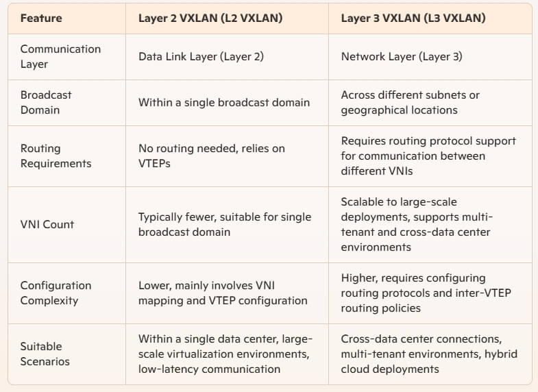
Comparison Between Layer 2 and Layer 3 VXLAN
Functionality Comparison
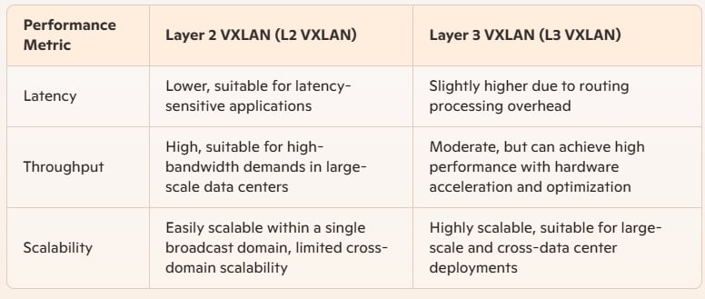
Performance Comparison
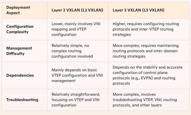
Deployment Complexity Comparison
Suitable Scenarios Comparison
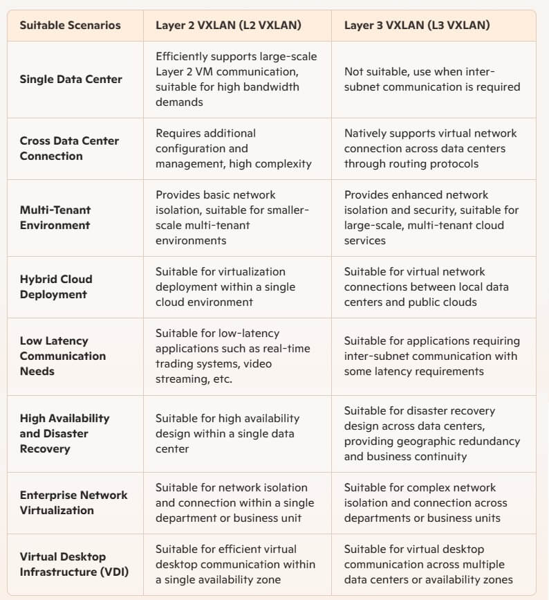
Layer 2 VXLAN and Layer 3 VXLAN each have unique functions and advantages, suited for different network needs and environments. Network administrators should consider specific business requirements, network scale, and environmental characteristics when designing and deploying VXLAN networks:
Choose L2 VXLAN: When the focus is on large-scale Layer 2 VM communication within a single data center, L2 VXLAN provides an efficient, low-latency solution that simplifies network management and configuration.
Choose L3 VXLAN: When virtual machines need to be connected across data centers, subnets, or geographical
