
The QSFP (Quad Small Form-factor Pluggable) transceiver module that uses an MPO (Multi-Fiber Push On) connector has become a must-have accessory in high-data-rate communication systems through 850nm multimode fiber connectivity. The purpose of this article is to describe how this transceiver module works, as well as the benefits and features of such components. Readers will understand the reasons for increasing efficiency and bandwidth through the operational concepts and coalescing technology into the present-day network design using the QSFP with MPO. We will also examine the effects of the environment on the use of the product and how it is relevant to current technologies.
What is a QSFP Transceiver Module?
Key Features of a QSFP Transceiver
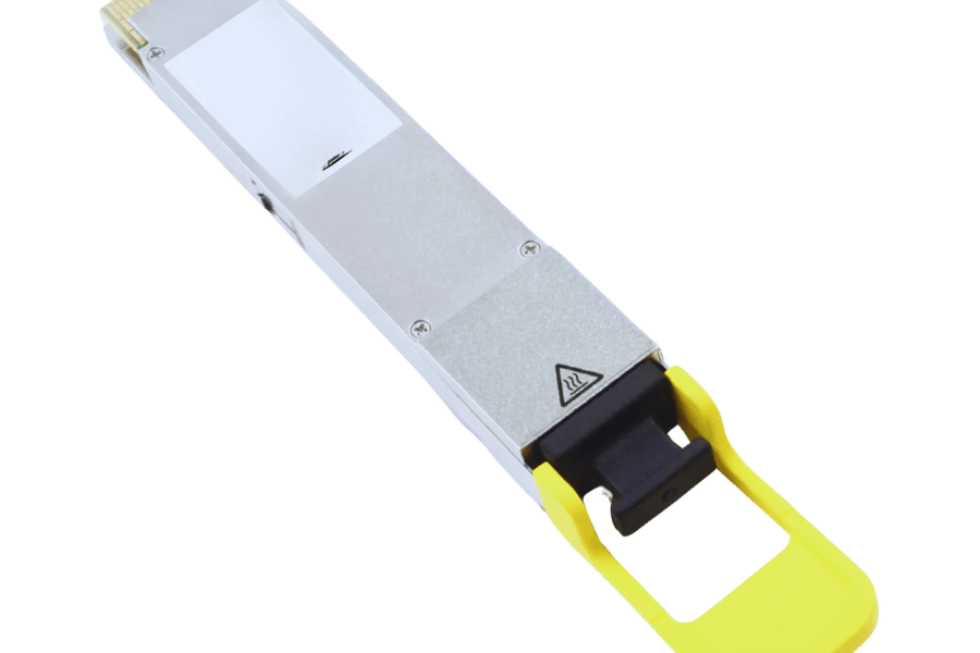
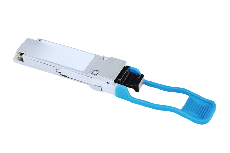
Among the salient attributes that primarily characterize the QSFP transceiver module and make the component an integral part of modern-day fiber optic systems are several attractive features. To begin with, the module has a tremendously high data rate performance of the order of 40 Gbps, or 40 gigabits per second, or even higher if one is ready to go deeper in terms of using more availed channels and for those who would wish to transmit short distances, multi-channel transmission works well. The dimensions of the form factor are small in groups so that several modules can fit together in network switches or routers densely in terms of space within data centers. Furthermore, although it has an emphasis on multimode fibers and nearly all the types of multimode fibers available, the QSFP transceiver can also interface with single-mode fibers, adding something to the effectiveness of the network. An MPO connector is also included, which allows attaching several fibers, making systems much simpler and larger in scale. Finally, the QSFP design is of constructive design that ensures they do not fail in was it the enhanced thermal management characteristics that make them and is applicable in areas of increased density.
How Does a QSFP Transceiver Work?
It is functional to change electrical signals into optical signals and vice versa with the help of the QSFP transceiver, which thus enables data transmission over optical fibers. During the switching phase of the process, the QSFP module receives incoming data in an electrical format from the networking switch, and the information is first light-modulated using a laser. MPO connectors allow the scattering of optical fibers so that each fiber can transmit a distinct information channel even when fused. Subsequently, on the receiving side, this process is reversed; the signals received are not electrical but optical signals, which are then processed and sent into the network for further processes. Factors that contribute to such an increase in the data throughput, as well as enhancement of the total capacity of the network, are also related to the performance of the module as a bidirectional and multicasting unit. DSP technology is further incorporated in the design, thus making it possible for the module to be used at a higher speed and at longer distances, which would have been a challenge in its operation.
Applications of QSFP Transceivers in Data Centers
Today’s data centers are engineered so that the QSFP transceivers are central to their architecture, thus enhancing data transmission performance irrespective of the network setup. The small form factor support and, therefore, high throughput can support many technologies, such as 100G Ethernet and InfiniBand connections, which are essential for massive data traffic. In a cloud computing environment, QSFPs make it faster to scale because the QSFP modules provide the much-needed bandwidth to deal with high data and virtualized traffic. Additionally, QSFP transceivers come with different types, which help improve the compatibility of networking devices, thereby justifying the future growth of data centers and investment. This flexibility not only minimizes area and power requirements but enhances operational performance as well, hence making QSFP transceivers the devices of choice for data center deployments.
What are the Specifications of the QSFP-40G-SR4?
Technical Specifications of QSFP-40G-SR4
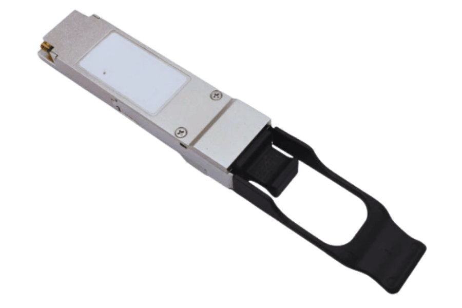
The QSFP-40G-SR4 transceiver is a multimode transceiver optimised for short distance communications. Its main specifications include the following:
- Data Rate: 40 Gbps
- Wavelength: 850 nm
- Distance: Maximum of 150 m on OM3 Multimode fiber and 400 m on OM4 multimode
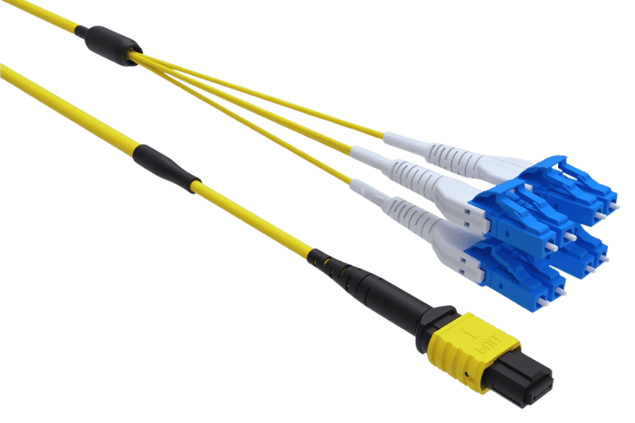
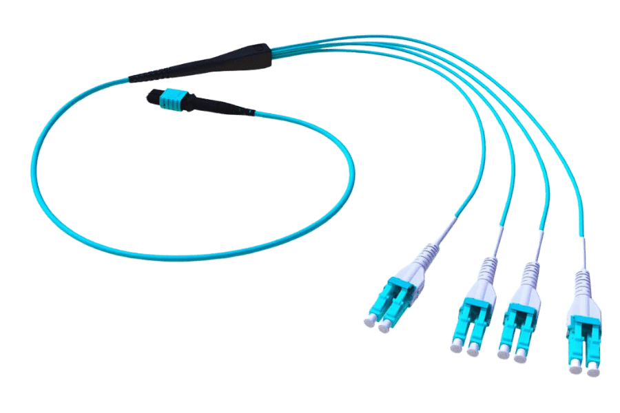
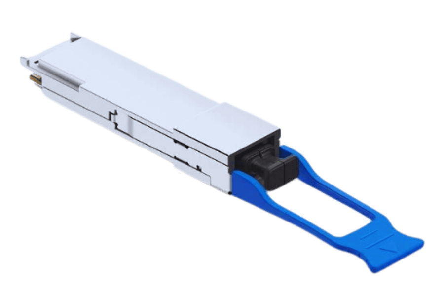
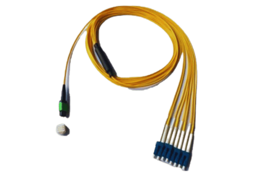
- Connector Type: MPO (Multi-Fiber Push-On)
- Number of Channels: 4.
- Transmitter Type: VCSEL
- Receiver Type: A PIN photodetector enhances the optical module’s performance for high data transmission applications over fiber.
- Power Consumption: 1.5W Less typically
- Operating Temperature Range: 0 – 70 degrees Celsius
These specifications make the QSFP-40G-SR4 module highly effective in high-density data center environments for achieving strong networking requirements.
Advantages of Using QSFP-40G-SR4 in 40G Ethernet
The QSFP-40G-SR4 transceiver comes with several benefits for 40G Ethernet implementations. One of its key attributes is the maximum transmission capability of 40 Gbps, which ensures fast data transfer in any environment in this age of data. Another favorable aspect of this transceiver is that latency is lowered, and the quality of the signals is enhanced on short distances due to multimode fiber optics rather than single-mode fibers. The compactness of the QSFP-40G-SR4 offers opportunities to strengthen density, thus optimizing the use of rack space as well as cable management. In addition, low power consumption of less than 1.5W minimizes electricity costs in data centers. Finally, the ability to leverage existing telecommunications equipment allows for deployment and enhancement of capacity in a manner that is convenient in the face of changing network headlines.
QSFP-40G-SR4 vs. Other Transceiver Modules
However, upon a broader analysis of other transceiver modules in comparison with the QSFP-40G-SR4, certain resolveable aspects are revealed, thus placing it in a unique perspective within the market of 40G QSFP solutions. For example, in relation to SFP+ (10G) transceiver modules, the QSFP-40G-SR4 has four times their data rate, making it more suitable for high bandwidth applications. Also, while these two types of devices can carry signals over multimode fiber, the effective distances for the QSFP module are much greater than those achieved with an SFP+ module, particularly when OM4 multimode is used.
Rather, instead of the common use of single-mode fiber, other 40G modules like the QSFP-40G-LR4 that offer such substantially longer range options, the QSFP-40G-SR4 are preferred in short-range applications due to the limitation of its transmission range at a wavelength of 850 nm which makes it most appropriate for high-density scenarios such as data centers where both space and signal integrity are at stake. In addition to that, the kind of connector that was selected was also a factor in the MPO in the specifications of the QSFP-40G-SR4, which facilitates greater density alignment, which is a feature in contemporary connectivity solutions than is provided by more common SFP+ modules which mostly employ LC connectors. In conclusion, the QSFP-40G-SR4 has been found to integrate various features, which include the high performance levels, efficiency, and versatility in its use in different networking situations, which makes it one of the preferred transceiver modules in the evolving information transmission technology.
How Does the MPO Connector Benefit Optical Networks?
Understanding MPO Connector Design
MPOs, or Multi-Fiber Push-On connectors, are specialized so that several optical fibers can be housed and connected onto one rectangular face plate. Such topography maximizes space usage, which is very important in a high-density data center-type environment. Each MPO connector is generally rated for 12 fiber connectors or 24 fiber connectors which substantially reduces the cable mass and also improves the overall cable management in the duplex applications.
However, the most essential characteristic of such connectors is that they allow multi-channel data transfer, significantly increasing the maximum transmittable data. Moreover, the type of optical fiber ribbon cable with MPO macro connectors allows mass fusion splicing without any interruptions in the cable. As the demand for bandwidth continues to compel change in networking technology, MPO connectors are fast becoming an absolute necessity in the MPO community. Moreover, MPO connectors are flexible and allow for expansion in the future, making them key elements in modern optical networks.
Benefits of MPO Connectors in Multimode Fiber Networks
MPO connectors, in general, have some benefits regarding multimode fiber systems, especially where high density is required. To begin with, their size does not waste any space since there is the possibility of having more than one fiber on a single duplex LC connector, thus reducing the size and making it easier to manage the cables. Additionally, supporting the high data rates ensures that one does not have to get the new infrastructure as the need for more capacity increases. Lastly, with these connectors, it is possible to create fast and painless deployments owing to the mass termination process, which greatly reduces the lead time and cost of 40G over 12-fiber optical links installation. Last but not least, their strength is also appreciated as this makes them more durable and reliable when their performance is concerned with adverse conditions, which is vital to network protection.
Compatibility of MPO Connectors with Fiber Optic Cables
MPO connectors are specifically designed to be compatible with multimode and single-mode fiber optic cables. In multimode applications, MPO connectors typically employ 62.5μm or 50μm core fibers that help to enhance high-bandwidth transmission. On the other hand, in single-mode applications, which employ MPO connectors, 9μm core fibers are commonly used to improve communication over longer distances by minimizing signal degradation. In addition, the fact that the MPO connectors are standard across different types of fibers also enhances compatibility, which helps build the existing networks regardless of the type of fiber optic cable installed. Therefore, the adaptability of MPO connectors contributes to the enhancement of interoperability in the different networks, thus catering to the diverse requirements of the infrastructure.
Why Choose 850nm for Multimode Fiber?
Characteristics of 850nm Wavelength
The 850nm wavelength is especially used for multimode fiber optic communication as it is rather favorable in the short-haul communication of data. To begin with, it has low absorption which leads to quite small attenuation or loss of the signal over a relatively smaller distance, usually up to 300m in OM3 and 400m in OM4 fibers. Secondly, the 850nm wavelength is well optimized to the peak emission range of the common VCSELs in use, thereby enhancing the efficient coupling of light into the multimode fiber’s core. Third, it enables high speeds of data transmission of at least 10 Gbps and more, which is quite necessary for modern-day data center interconnects and high-speed networking end applications. In conclusion, the parameters of the 850nm wavelength make the multimode fiber optic system work optimally and efficiently.
Performance of 850nm in Multimode Fiber
The 850nm wavelength in multimode fiber systems provides exceptional performance with respect to the maintenance of signal integrity and bandwidth for diverse applications. The multimode fibers at this wavelength also have lower modal dispersion, resulting in less signal distortion and less bit error at short distances, which is important for 10GBASE-SR applications. This means better functioning in data-saturated areas such as data centers where datarates exceeding 10 Gbps are possible. Again, when using 850nm as the transmitting wavelength, several light paths are achieved in the fiber increasing data throughput and scalability. On the whole, the persistence of the performance of 850nm in multimode fiber makes it possible to meet the new networking challenges and protect capital investments in infrastructure.
Comparing 850nm with Other Wavelengths
The moment one attempts to compare the optical fiber with the 850 nm wavelength to others such as the 1310 nm and the 1550 nm becomes when the properties and characteristics determine the use and efficiency of the 40G over 12-fiber optical links. The primary purpose for which the wavelength of 1310nm was developed – its loss over longer distances, is evident with 850nm sheath, but it breaches the modal bandwidth ubiquitous in multimode fibers, therefore shortening the lengths of the data rates. On the other hand, the 1550nm wavelength is the one preferred for use in single-mode fibers where even lower losses of the fiber are found and where it is possible to transmit to distances greater than 40 kilometers, which is where it’s restricted to; it still loses out on the advantages of the multimode fibers that are ineffective at such travel. In conclusion, the 850nm is the most appropriate for high-speed transmission over short distances, especially within environments such as data centers. In contrary, of the wavelengths, 1310nm and 1550nm are used mainly with single mode fibres where long distances are the major requirement.
What is the DDM Feature in Optical Transceivers?
Benefits of Digital Diagnostic Monitoring (DDM)
Digital Diagnostic Monitoring (DDM) is one of the significant features of the optical transceivers which is responsible for monitoring the parameters of the devices Readily. Continuous monitoring of DDM is one of the most useful points, and it is possible to monitor parameters such as temperature, supply voltage, and optical output power. Such a provision allows for maintenance of the system and detection of potential problems in a timely way before they cause systems failures thus increasing system reliability. In addition to that, DDM makes it possible to increase operational performance too, for example, lower attention minutes, as it allows network administrators to make appropriate use of real-time data analytics, meaning beneficiary factors of the aesthetics and the continuity of the network are reduced. Moreover, DDM of the networks also considers the specifications and standards set by the Telecommunications Industry Association (TIA), among others, thereby enhancing the use of DDM technology effectively, making it easy to incorporate with existing network management tools. All these advantages demonstrate how DDM is important in providing strong and high-performance optical networks.
How DDM Enhances Network Performance
Digital Diagnostic Monitoring (DDM) makes it easier to improve the performance of networks by giving the required information for the optimal management of optical transceiver systems.By examining various factors like optical power, temperature, and voltage regularly and at a constant interval, DDM makes it easy to see and fix any issues that may threaten performance very quickly. Such prompt actions enable the signal integrity to be preserved, and the danger of data being lost or transmission errors happening is minimized. Not only that but DDM data can be assimilated into the systems used to manage the network, thus monitoring traffic and re-routing changes depending on how busy it is. Thus, the bandwidth is managed in a more effective manner, and the quality of service is enhanced while the latency of the system decreases and its robustness increases. In addition to that, regulation by standards also ensures that network parts function within certain limits, leading to reduced downtimes and improved quality over time.
Implementing DDM in QSFP Transceivers
The following factors must be addressed to successfully implement Digital Diagnostic Monitoring (DDM) in Quad Small Form-factor Pluggable (QSFP) transceivers. First, one important step is to choose QSFP transceivers that are DDM compliant, because not all transceivers are DDM compliant. Manufacturers such as Cisco Rest and Finisar, however, offer QSFP models with incorporated DDM, which makes it possible to track important operational parameters in detail.
Next, it is also necessary that the network management tools in question can handle such DDM data format. They must also remain compatible with the existing SNMP (Simple Network Management Protocol) management solutions in order to integrate and monitor by alerting DDM metrics in real-time. At the same time, optical network management software has been employed, which has enhanced the DDM data visualization from the fiber transceiver for performance indicators rendering and decision-making support.
Finally, personnel training to efficiently read DDM data is very important if DDM is to be well integrated and used to its full potential. Furthermore, knowing when and how different optical power levels, temperature, and voltage should be included allows the network teams to deal with problems that might cause service disruptions in a proactive manner, which will keep the network running as desired for a longer time.
How to Ensure Compatibility with Cisco QSFP-40G-SR4?
Checking Compatibility with Cisco Switches
As a starting point and to check the QSFP-40G-SR4 transceiver compatibility with Cisco switches, one should first look into the official Cisco compatibility matrix that specifies the transceiver modules that are supported for various switch models. This matrix contains vital details on what types of switches are capable of supporting the QSFP-40G-SR4 and hence assisting in aligning the hardware configurations with the specifications by Cisco.
Furthermore, make sure that the switch firmware is up to date since in some cases incompatibilities can be resolved through the latest features for the optical module. Finally, think about how the transceiver is going to be used because different environments may have different conditions, such as distance and speed, which the Cisco switch has to support. In this manner, network administrators are able to satisfactorily ascertain the QSFP-40G-SR4 compatibility with the Cisco infrastructure.
Using QSFP-40G-SR4 with Cisco Networking Equipment
It is important to properly configure any hardware that comes into play when working with the Cisco Network QSFP-40G-SR4 transceiver. To begin installation, the transceiver should be locked on any open port on the Cisco switch to avoid any security vulnerabilities. After the transceiver has been installed on the switch, suitable management settings should be configured in the switch’s management interface to support it. This could involve enabling link aggregation as well as other features or changing the port parameters.
Moreover, it is important to track the transceiver’s performance while using the diagnostic utilities available on the switch. Some of the parameters that may be evaluated are the levels of optical power and the error rate. Such monitoring is forward-looking in the sense that it helps to mitigate problems that can compromise the network’s efficiency or reliability. These are the recommended guidelines with which network administrators can take full advantage of the capabilities of QSFP-40G-SR4 in the Cisco networking environment.
Best Practices for Integrating QSFP-40G-SR4 in Cisco Networks
The following considerations should be considered to ensure flawless integration of Cisco compatible active optical connections and the QSFP-40G-SR4 transceiver within Cisco networks.
- Verification of Compatibility Prior to Installation: Prior to installation, ensure that there is a technical fit between the transceiver and switch model based on the manufacturer’s data sheets and compatibility matrices.
- Correct Procedure during the Insert: QSFP-40G-SR4 is to be placed inward the reported port, and the latch is to be pushed down to make the connection secure once again. Do not apply excessive force as this could cause an injury.
- Settings Configuration: For example, go to the administrative interface of switch operation management systems and approve criteria that will link aggregation where necessary or modify the parameters of transmit and receive in order to improve output.
- Performance monitoring of the fiber transceiver is very important for optimum network use. After the switch has been integrated, the diagnostic functions built into the network switching device have to be used to measure optical power levels, signaling quality, and error rates. Routine inspection will facilitate anticipation of potential performance hindrance.
- Upgrading Firmware: When upgrading the switch, it is enough to verify that one has the latest firmware upgrade to avoid going to the base level. This may improve support and quality of the QSFP-40G-SR4.
Thus, compliance with these practices enables a network administrator to satisfactorily incorporate and maintain the QSFP-40G-SR4 transceiver while enabling the construction of a strong, performing, and reliable network for all the fiber transceiver connections made.
Reference Sources
Frequently Asked Questions (FAQs)
Q: What is a QSFP Transceiver Module with MPO Connector for 850nm Multimode Fiber?
A: A QSFP Transceiver Module with an MPO Connector for 850nm Multimode Fiber is a type of optical transceiver module that is typically 40 gigabit Ethernet oriented. It permits the transmission of data through multimode fiber optic cables.
Q: What is the range of the 40GBASE-SR4 QSFP Transceiver Module?
A: The maximum link distance for the 40GBASE-SR4 QSFP Transceiver Module is 100m for the OM3 type of multimode fiber optic cable.
Q: Is using the QSFP Transceiver Module with fiber patch cables possible?
A: Indeed, yes, the QSFP Transceiver Module is compatible with a variety of fibre patch cable types, including MPO-penned ones for high-bandwidth 40G optical links.
Q: Does the 40GBASE-SR4 QSFP Transceiver Module meet IEEE specifications?
A: Yes, the design of the 40GBASE-SR4 QSFP Transceiver Module meets the requirements of 802.3ba for 40 Gigabit Ethernet.
Q: What type of fiber cable is used in the 40GBASE-SR4 QSFP Transceiver Module?
A: The 40GBASE-SR4 QSFP Transceiver Module is optimized for use with OM3 or OM4 multimode fiber cables for up to a distance of 100m.
Q: In what manner is the breakout functionality incorporated in the QSFP Transceiver Module?
A: The breakout functionality permits a single QSFP Transceiver Module to interface with several SFP transceivers or ports via a breakout cable, thus allowing 10G connections to arise from a single 40G interface.
Q: State the 40GBASE-SR4 QSFP Transceiver Module form factor.
A: The form factor of the 40GBASE-SR4 QSFP Transceiver Module is that of a QSFP, that is, a Miniaturized Hot Pluggable Transceiver orientation standard that is used widely for high data rate transmissions.
Q: Is it possible to insert the QSFP Transceiver Module into a fiber media converter?
A: It can. The QSFP Transmitter module can, moreover, be used in conjunction with a fiber media converter to change one type of network medium to a different one, for instance, from optical to 10GBASE-SR fiber media.
Q: What are the uses of the QSFP Transceiver Module with an MPO Connector?
A: The most common application of the QSFP Transceiver Module with MPO Connector is in building 40G optical links in Data Centers, Enterprise, and High-performance Computing Networks.