
Market Forecast and Application Scenarios
The emergence of new services such as 4K virtual reality (VR), Internet of Things, and cloud computing has put forward higher requirements on network bandwidth, concurrency, and real-time performance. According to Omdia’s forecast, as bandwidth demand continues to increase in the next few years, although 100, 200, and 400 Gbit/s optical transceiver will still have the largest market share, 800 Gbit/s optical transceiver will be deployed on a large scale in 2025.
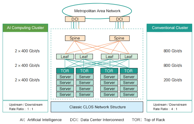
Figure 1: 800GE network architecture diagram
As shown in Figure 1, according to the 800 GE network structure, the connection distance from the top-of-rack switch (TOR) to the Leaf switch can be as short as tens of meters or as long as hundreds of meters. For this part of the connection, large Internet companies generally adopt 100 Gbit/s connection technology, and have been gradually upgrading to 200 Gbit/s or 400 Gbit/s technology starting since 2021. Some leading companies began trials of 800Gbit/s technology in 2023. The connection from Leaf to Spine switch, or from Spine switch to core router, may solve the interconnection problem within a campus or between adjacent campuses. The connection distance can reach 2 km or even 10 km. The interface rate was gradually upgraded from 100 Gbit/s to 200 Gbit/s or 400 Gbit/s starting from 2021. Data Center Interconnection (DCI) generally refers to the connection between several adjacent data centers for load balancing or disaster recovery backup. The connection distance may be as long as tens of kilometers. For such a long distance, since optical fiber resources are relatively precious, people mainly use dense wavelength division multiplexing plus coherent communication to reuse optical fiber resources as much as possible. We divide the application scenarios of 800 Gbit/s optical transceiver into SR (100 m scenario), DR/FR/LR (500 m/2 km/10 km scenario), and ER/ZR (40 km/80 km scenario).
Technical Solution
Program Overview
The 800 Gbit/s technical solution evolution includes 3 generations. The first generation is 8 optical and 8 electrical solution: the optical interface is 8×100 Gbit/s, the electrical interface is 8×100 Gbit/s, and the commercial time is 2021; The second generation is 4 optical and 8 electrical solution: optical interface 4×200 Gbit/s, electrical interface 8×100 Gbit/s, commercially available in 2024; The third generation is 4 optical and 4 electrical solution: optical interface 4×200 Gbit/s, electrical interface 8×100 Gbit/s, expected to be commercially available in 2026. In the long term (within 5 years), optical/electrical single-channel 200 Gbit/s technology will be popularized; In the short term (within 3 years), since single-channel 200 Gbit/s optoelectronic chip devices and equalization technology are not yet mature, the industry still needs time to break through the relevant technical bottlenecks.
Electrical interface and packaging
We can tell from the development of 100 Gbit/s direct modulation and direct detection optical transceiver, when the single-channel rate of the electrical interface is the same as that of the optical interface, the architecture of optical transceiver will reach the optimal state with the advantages of low power consumption and low cost. A single-channel 100 Gbit/s electrical interface will be the ideal electrical interface for 8×100 Gbit/s optical transceiver, and a single-channel 200 Gbit/s electrical interface will be the ideal electrical interface for 4×200 Gbit/s optical transceiver. In terms of packaging, 800 Gbit/s optical transceiver may exist in different forms such as double-density quad small form factor pluggable (QSFPDD800) and octal small form factor pluggable (OSFP). Due to factors such as wiring within the module and connector loss, pluggable optical transceiver based on 200 Gbit/s electrical interfaces still face many challenges.
Optical Interface
There are three main types of 800 Gbit/s optical transceiver optical interface architectures, as shown in Figure 2. (1) 8×100 Gbit/s 4-level pulse amplitude modulation (PAM4) optical transceiver: The PAM4 transceiver operates at 53 Gbd and uses 8 pairs of digital-to-analog converters (DACs) and analog-to-digital converters (ADCs), 8 lasers, 8 pairs of optical transceivers, and 1 pair of 8-channel coarse wavelength division multiplexer (CWDM) or Ethernet channel-based wavelength division multiplexing (LAN-WDM) (depending on the fiber dispersion loss) multiplexer and demultiplexer (not required for SR/DR application scenarios). (2) 4×200 Gbit/s PAM4 optical transceiver: The PAM4 transceiver operates at 106 Gbd, using 4 pairs of DACs and ADCs, 4 pairs of optical transceivers (including 4 lasers), and 1 pair of 4-channel CWDM or LAN-WDM (depending on the fiber dispersion loss) multiplexer and demultiplexer (not required for SR/DR application scenarios). (3) 800 Gbit/s coherent optical module: operates at 128 Gbd under dual-polarization sixteen quadrature amplitude modulation (16QAM). It uses 4 pairs of DACs and ADCs, 1 laser, and 1 pair of optical transceivers, enabling the use of fixed-wavelength lasers in data center coherent optical modules to reduce cost and power consumption.
Figure 2: Three optical interface architectures of 800Gbit/s optical transceiver
The 8×100 Gbit/s direct adjustment and direct inspection solution can utilize the existing technical architecture. The relevant technologies and standards are relatively mature, and the supply chain is also relatively complete. In the SR scenario, vertical cavity surface emitting laser (VCSEL) 100 Gbit/s technology faces challenges. Improving the performance of multimode solutions and reducing the cost of multimode optical fiber will be key factors in the continued evolution of this technology. single mode technologies represented by silicon photonics (SiPh) and directly modulated lasers (DML) are developing rapidly. Among them, SiPh technology is developing more rapidly, expected to compete with multi-mode solutions in application scenarios with transmission distances of 100 m and below in the future. In the DR/FR scenario, there are three solutions: electro-absorption modulated laser (EML), DML and SiPh.
In the LR scene, There are 800 Gbit/s LR8 schemes based on coarse wavelength division multiplexing (CWDM), lan wavelength division multiplexing (LWDM) and narrowband lan wavelength division multiplexing (nLWDM), which are still in the research stage. In terms of wavelength selection, due to the large dispersion of the O-band edge wavelength, LWDM8 is superior to CWDM8 in terms of dispersion penalty. Currently, direct adjustment and direct inspection solutions for distances of 10 km and above are mainly faced with the challenges of “worst case” dispersion and narrow dispersion tolerance matching.
Building a new wavelength system and compressing the multi-channel wavelength range can narrow the worst-case dispersion accordingly, thereby simplifying the digital signal processing (DSP) design and reducing theoretical power consumption. For example, the dispersion-limited distance of an 8×100 Gbit/sPAM4 direct modulation and direct detection solution is about 10 km when the LWDM solution with 800 GHz spacing is adopted. When the nLWDM solution with 400 GHz spacing is adopted, the dispersion-limited distance can be extended to 20 km. When the nLWDM solution with 200 GHz spacing is adopted, the dispersion-limited distance can be further extended to 40 km. At the same time, compressing the zero dispersion point distribution or drift range and reducing the corresponding dispersion range is also one of the solutions. However, since the distribution of zero dispersion points of optical fiber products from different manufacturers is not uniform, it is still difficult to realize large-scale compression.
For the 4×200 Gbit/s direct modulation and direct detection solution, a single-channel 200 Gbit/s continues to use the PAM4 modulation code type, and can take advantage of the relatively mature PAM4 industrial infrastructure (but the possibility of new modulation code types is not ruled out). In the 4×200 Gbit/s DR and FR application scenarios, there are currently two technical solutions: 4-channel single mode parallel (PSM4) and CWDM4.
These two solutions still face many challenges and require further research. For LR application scenarios, there are 800 Gbit/s LR4 solutions based on CWDM, LWDM, and nLWDM. These solutions are still in the research and discussion stage and require high-bandwidth optoelectronic chip devices, stronger equalization technology and forward error correction (FEC) to ensure the corrected bit error rate (BER). The device bandwidth of 800 Gbit/s coherent optical modules needs to be greatly improved, and it is difficult to double the bandwidth in one step. The 800 Gbit/s coherent optical module based on 96 GBd devices must adopt higher-order modulation code types. This method has disadvantages such as low optical signal-to-noise ratio (OSNR), limited transmission distance and application scenarios. The 128 GBd-based dual polarization (DP)-16QAM coherent optical module has better OSNR and transmission capacity and will become the mainstream implementation solution for 800 Gbit/s coherent.
FEC
FEC is generally divided into three categories: end-to-end FEC, nested cascade FEC, and segmented FEC. It is generally believed in the industry that the application of 8×100 Gbit/s direct modulation and direct detection solution within a transmission distance of 40 km can be achieved by end-to-end KP4 FEC. For a transmission distance of 40 km, a stronger FEC may be used.
The 4×200 Gbit/s direct modulation and direct detection solution has a higher rate and therefore requires the introduction of a new BER standard, a new FEC coding method and a more complex equalizer. The IEEE 802.3 B400G SG (Institute of Electrical and Electronics Engineers 802.3 Post-400 Gbit/s Study Group) and 800G Pluggable MSA (800 Gbit/s Pluggable Multi-Source Agreement) working groups have started relevant discussions. The cascade method may become a new path for 4×200 Gbit/s direct modulation and direct detection solutions. This approach not only retains KP4 FEC and avoids the extra cost of integrating new FEC in the main chip, but also provides additional protection for the optical link through the lightweight and easy-to-implement FEC in optical transceiver, reducing the power consumption and latency caused by decoding. In terms of error correction performance, various cascaded inner codes such as KP4+BCH (144,136) can reduce the post-correction range to less than 1E-13 based on the pre-correction bit error rate range of 1 to 2E-3. At the same time, the strongest demand for 800 Gbit/s currently comes from OTT (Internet operators) data centers and high-performance computing scenarios. These scenarios have high requirements for latency sensitivity. Low-latency FEC algorithm has become one of the core demands of 800 Gbit/s.
800 Gbit/s coherence includes 800 Gbit/sLR and 800 Gbit/s ZR. Therefore, we need to design FEC algorithms for different application scenarios. (1) The 800LR scenario requires a 10 km campus network, which has high requirements for latency and power consumption. Currently, the solutions include KP4+eHamming/eBCH cascade, spatial coupled code FEC (XR-FEC), clustered FEC (CFEC), Zipper, lightweight open FEC (OFEC), etc. Among them, the cascade solution has something in common with the 4×200 Gbit/s direct modulation and direct detection cascade solution. The connection between the two paths can further reduce the complexity of the main chip. (2) The 800ZR scenario is mainly used in DCI and is a continuation of the Optical Internetworking Forum (OIF) 400ZR standard. 800ZR uses the DP-16QAM modulation format, which poses a certain challenge to the CFEC capability. It may require FEC solutions with stronger error correction capabilities, such as multi-level coding (MLC) and OFEC.
Equalization Technology
To achieve a single-channel data transmission rate of 200 Gbit/s, optoelectronic chips must undergo performance upgrades, such as 200 Gbit/s SerDes, optoelectronic chips and devices with a bandwidth higher than 50 GHz, etc. According to current technical research reports, optical chips with bandwidths higher than 50 GHz are relatively easy to achieve. How to ensure the optimal performance of other indicators while improving bandwidth is the key point to consider. Currently, the bandwidth of Driver and TIA electrical chips cannot meet the rate requirements and also requires balancing capabilities. While improving their own bandwidth, these electronic chips need to achieve system-level signal optimization effects. Efficient equalization technology can greatly relax the system’s requirements on the bandwidth of optoelectronic devices.
Common equalization techniques include feed-forward equalization (FFE), decision feedback equalization (DFE), and maximum likelihood sequence equalization (MLSE). Among them, FFE is widely used in SerDes systems and optical signal DSP (oDSP) chips due to its simple implementation. In order to alleviate the demand for optoelectronic device bandwidth of single-channel 200 Gbit/s, on the one hand, FFE pre-equalization technology can be used at the transmitter to compensate for the bandwidth of the transmitter device; on the other hand, more powerful equalization technology can be applied in oDSP to alleviate the impact of bandwidth limitation on system performance degradation. For the 5-tap FFE equalization used in the single-wavelength 100 Gbit/s standard, when the rate is increased to 200 Gbit/s, the number of FFE taps will increase. Although a higher performance MLSE equalization algorithm can also be used as a solution, the MLSE implementation is more complex and requires a large amount of computation, which will increase the power consumption of oDSP.
Related Products:
-
 NVIDIA MMS4X50-NM Compatible OSFP 2x400G FR4 PAM4 1310nm 2km DOM Dual Duplex LC SMF Optical Transceiver Module
$1350.00
NVIDIA MMS4X50-NM Compatible OSFP 2x400G FR4 PAM4 1310nm 2km DOM Dual Duplex LC SMF Optical Transceiver Module
$1350.00
-
 NVIDIA MMS4X00-NM-FLT Compatible 800G Twin-port OSFP 2x400G Flat Top PAM4 1310nm 500m DOM Dual MTP/MPO-12 SMF Optical Transceiver Module
$1200.00
NVIDIA MMS4X00-NM-FLT Compatible 800G Twin-port OSFP 2x400G Flat Top PAM4 1310nm 500m DOM Dual MTP/MPO-12 SMF Optical Transceiver Module
$1200.00
-
 NVIDIA MMA4Z00-NS-FLT Compatible 800Gb/s Twin-port OSFP 2x400G SR8 PAM4 850nm 100m DOM Dual MPO-12 MMF Optical Transceiver Module
$850.00
NVIDIA MMA4Z00-NS-FLT Compatible 800Gb/s Twin-port OSFP 2x400G SR8 PAM4 850nm 100m DOM Dual MPO-12 MMF Optical Transceiver Module
$850.00
-
 NVIDIA MMS4X00-NM Compatible 800Gb/s Twin-port OSFP 2x400G PAM4 1310nm 500m DOM Dual MTP/MPO-12 SMF Optical Transceiver Module
$1100.00
NVIDIA MMS4X00-NM Compatible 800Gb/s Twin-port OSFP 2x400G PAM4 1310nm 500m DOM Dual MTP/MPO-12 SMF Optical Transceiver Module
$1100.00
-
 NVIDIA MMA4Z00-NS Compatible 800Gb/s Twin-port OSFP 2x400G SR8 PAM4 850nm 100m DOM Dual MPO-12 MMF Optical Transceiver Module
$750.00
NVIDIA MMA4Z00-NS Compatible 800Gb/s Twin-port OSFP 2x400G SR8 PAM4 850nm 100m DOM Dual MPO-12 MMF Optical Transceiver Module
$750.00
-
 OSFP-800G-SR8 OSFP 8x100G SR8 PAM4 850nm MTP/MPO-16 100m OM4 MMF FEC Optical Transceiver Module
$750.00
OSFP-800G-SR8 OSFP 8x100G SR8 PAM4 850nm MTP/MPO-16 100m OM4 MMF FEC Optical Transceiver Module
$750.00
-
 QSFP-DD-800G-SR8 800G SR8 QSFP-DD 850nm 100m OM4 MMF MPO-16 Optical Transceiver Module
$1200.00
QSFP-DD-800G-SR8 800G SR8 QSFP-DD 850nm 100m OM4 MMF MPO-16 Optical Transceiver Module
$1200.00
-
 QSFP-DD-800G-DR8 800G-DR8 QSFP-DD PAM4 1310nm 500m DOM MTP/MPO-16 SMF Optical Transceiver Module
$1300.00
QSFP-DD-800G-DR8 800G-DR8 QSFP-DD PAM4 1310nm 500m DOM MTP/MPO-16 SMF Optical Transceiver Module
$1300.00
-
 OSFP-800G-DR8D 800G-DR8 OSFP PAM4 1310nm 500m DOM Dual MTP/MPO-12 SMF Optical Transceiver Module
$1100.00
OSFP-800G-DR8D 800G-DR8 OSFP PAM4 1310nm 500m DOM Dual MTP/MPO-12 SMF Optical Transceiver Module
$1100.00
-
 QSFP-DD-800G-2FR4L QSFP-DD 2x400G FR4 PAM4 CWDM4 2km DOM Dual duplex LC SMF Optical Transceiver Module
$4000.00
QSFP-DD-800G-2FR4L QSFP-DD 2x400G FR4 PAM4 CWDM4 2km DOM Dual duplex LC SMF Optical Transceiver Module
$4000.00